
Device and process for directly reducing smelt antimony from antimony slag and antimony ash

A soot and antimony slag technology, applied in the direction of improving process efficiency, can solve the problems of increasing fuel consumption, reducing smelting cost, and large antimony circulation amount, and achieves the goal of reducing fuel consumption, strong adaptability of raw materials, and high degree of process automation. Effect

Inactive Publication Date: 2016-05-25
HENAN YUGUANG GOLD & LEAD
View PDF8 Cites 18 Cited by
  • Summary
  • Abstract
  • Description
  • Claims
  • Application Information

AI Technical Summary

Problems solved by technology

At present, in terms of antimony smelting technology, the use of bottom blowing or side blowing molten pool melting technology has solved the environmental protection problem of smelting operations, improved the reaction rate and thermal efficiency, and reduced energy consumption, but there are also some shortcomings. Antimony oxide reduction The smelting process is all produced and operated in a negative pressure environment. The soot is added directly, and the raw materials taken away by the flue gas are large, resulting in a high soot rate, a large amount of antimony in the production system, and a low direct recovery rate of antimony; The addition method of granulation is also difficult to enter the melt to quickly participate in the reaction and slagging, and the addition of water in the granulation process requires additional heat source consumption in the reduction smelting process and increases fuel consumption; the fuel used in the reduction reaction process is mostly price High natural gas or coal gas is not conducive to the reduction of smelting costs

Method used


Image

  • Device and process for directly reducing smelt antimony from antimony slag and antimony ash
  • Device and process for directly reducing smelt antimony from antimony slag and antimony ash

Examples


Embodiment Construction

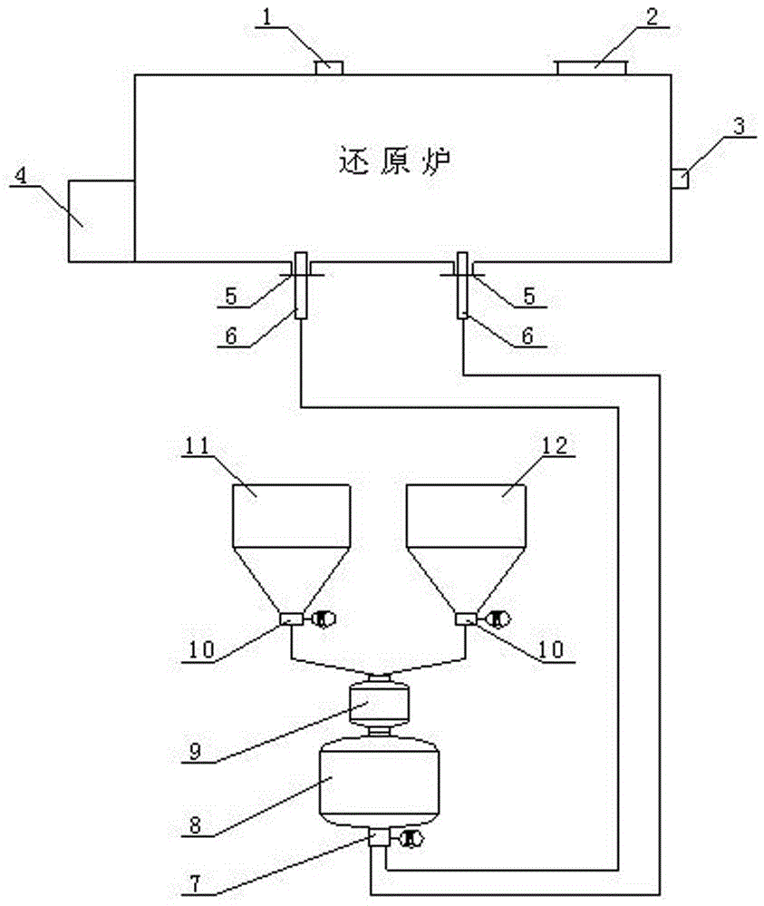
[0028] Such as figure 1 As shown, a device for direct reduction of antimony slag and antimony soot to smelt antimony includes a cylindrical horizontal reduction furnace that rotates along the axis. There are two spray gun ports 5 in the lower part of the reduction furnace, and spray gun ports 5 are equipped with spray guns 6. There is a feeding port 1 and a smoke outlet 2 on the upper part of the furnace, and a flue gas dust collection system is provided outside the smoke outlet 2. One end of the reduction furnace is opened with a slag outlet 3, and the other end is opened with an antimony outlet. 4. The reduction furnace is also connected with an antimony soot supply system and a pulverized coal supply system. The antimony soot supply system includes an antimony soot bin 11 and a spiral weighing scale 10 connected to the lower part of the antimony soot bin 11. The pulverized coal supply system includes a pulverized coal bin 12 Connected to the screw metering scale 10 at the b...


PUM

PropertyMeasurementUnit
particle diameteraaaaaaaaaa
particle sizeaaaaaaaaaa

Abstract

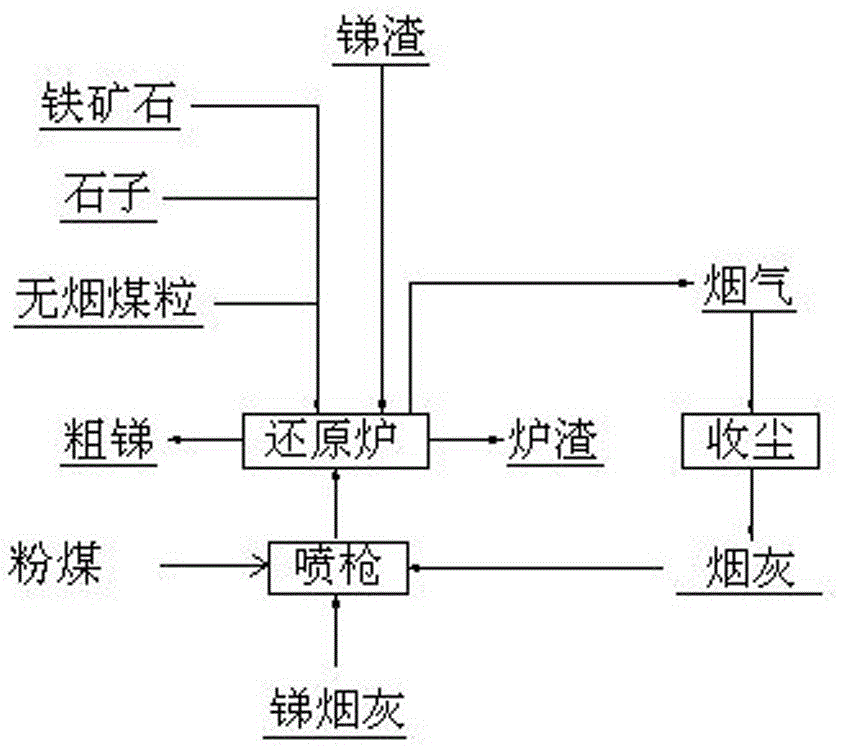
The invention relates to the non-ferrous metal metallurgy industry, in particular to a device and a process used for directly reducing smelt antimony from antimony slag and antimony ash and having the characteristics of short process, low energy consumption and high applicability. A reduction furnace comprises an antimony ash supply system, a powdered coal supply system and a flue gas dust collection system. The antimony slag is directly fed into the reduction furnace; iron ores, pebbles and anthracite particles are continuously supplied into the reduction furnace and serve as a slag former and a reducer at the same time; and the antimony ash, ash collected by the flue gas dust collection system and powdered coal as fuel are blown into the reduction furnace through a spray gun, so that materials in the reduction furnace are enabled to quickly produce a reduction reaction. The device and process are short in technological process, high in reduction degree, high in antimony direct recovery rate and low in energy consumption; and in addition, the environmental pollution is alleviated and the labor intensity is reduced.

Description

technical field [0001] The invention relates to the nonferrous metal smelting industry, in particular to a device for directly reducing antimony smelting antimony slag and antimony soot with short flow, low energy consumption and strong applicability and a process thereof. Background technique [0002] In my country, antimony sulfide, antimony oxide concentrate or raw ore are used as raw materials. Antimony smelting methods include wet method and fire method. Among them, the wet method has the disadvantages of large amount of wastewater and high treatment costs. The most commonly used process for pyroprocessing is blast furnace volatilization smelting-reverberatory furnace reduction. During the smelting process, antimony volatilizes and oxidizes, and the antimony-containing dust is obtained through flue gas dust collection. The antimony-containing dust is mixed with soda ash, coal, and iron filings, and then enters the reverberatory furnace for reduction to produce crude ant...

Claims


Application Information

Patent Timeline
Patent Type & Authority Applications(China)
IPC IPC(8): C22B7/02C22B7/04C22B30/02
CPCC22B7/001C22B7/02C22B7/04C22B30/02Y02P10/20
Inventor 李卫锋徐诗艳狄聚才杨明
Owner HENAN YUGUANG GOLD & LEAD
Learn More