
High-thermal conductivity resin composition and application thereof

A resin composition and high thermal conductivity technology, which is applied in the field of metal-based copper-clad laminates and high-thermal-conduction resin compositions, can solve the problems of reducing the interface binding between resin and thermally conductive fillers, defects in the electrical properties of metal-based copper-clad laminates, and reduced breakdown voltage. , to achieve the effects of high peel strength, high breakdown voltage and high thermal conductivity

Active Publication Date: 2016-06-01
SHAANXI SHENGYI TECH
View PDF4 Cites 34 Cited by
  • Summary
  • Abstract
  • Description
  • Claims
  • Application Information

AI Technical Summary

Problems solved by technology

Among them, the Chinese patent with application number 200910189544.6 (application date: 2009.11.24, publication number: 101735611, publication date: 2011.6.16) is made by adding high thermal conductivity fillers into the BMI resin system modified by allylphenol Copper clad laminate has excellent heat resistance and electrical properties, but its thermal conductivity is less than 1.0W / m·K, even if the reinforcing material is removed, the thermal conductivity is less than 1.5W / m·K
[0004] In the BMI resin system modified by allylphenol in addition, although the toughness of the cured product can be further improved by flexible resins such as nitrile rubber, phenolic resin and other large molecular weight flexible substances, because nitrile rubber, phenol Oxygen resin has a large molecular weight, which forms a "sea island" structure in the curing system, which reduces the interfacial bonding between the resin and the thermally conductive filler, and brings defects to the electrical properties of the metal-based copper clad laminate, especially under high temperature and high humidity conditions. rapid drop in voltage

Method used


Image

  • High-thermal conductivity resin composition and application thereof
  • High-thermal conductivity resin composition and application thereof
  • High-thermal conductivity resin composition and application thereof

Examples

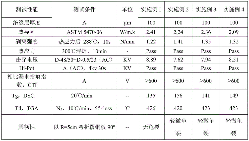

Embodiment 1~5 and comparative example 1~2

[0041] Each component used in the epoxy resin composition of embodiment 1~5 and comparative example 1~2 and content (by weight) are as shown in table 1; Each component code and its corresponding component name are as follows Shown:

[0042] (A) bismaleimide modified epoxy resin:

[0043] (A1) N-p-carboxyphenylmaleimide modified epoxy resin: prepared by reacting N-p-carboxyphenylmaleimide and bisphenol A novolak epoxy resin;

[0044] (A2) Diamine and bismaleimide compound modified epoxy resin: prepared by the copolymerization reaction of diaminodiphenyl sulfone, diphenyl ether bismaleimide and bisphenol A novolac epoxy resin;

[0045] (A3) Dihydric phenol and bismaleimide compound modified epoxy resin: prepared by copolymerization of allyl bisphenol A, diphenyl ether bismaleimide and bisphenol A epoxy resin;

[0046] (B) Flexible modified epoxy resin:

[0047] (B1) organosilicon modified epoxy resin, produced by Korea SHIN-A company;

[0048] (B2) Rubber modified epoxy resi...


PUM

PropertyMeasurementUnit
Thicknessaaaaaaaaaa
Thermal conductivityaaaaaaaaaa

Abstract

The invention discloses a high-thermal conductivity resin composition. The high-thermal conductivity resin composition is prepared from the following components in parts by weight: 40 to 75 parts of BMI (Bismaleimides) modified epoxy resin, 5 to 40 parts of flexible modified epoxy resin, 360 to 480 parts of thermal conducting fillers, 8 to 30 parts of curing agent, 2 to 6 parts of coupling agent, 0.05 to 0.85 part of curing accelerator and 1 to 5 parts of additive. According to the high-thermal conductivity resin composition disclosed by the invention, by introducing the BMI modified epoxy resin in a system, the advantages of epoxy resin and BMI are integrated; meanwhile, the flexible modified epoxy resin and the thermal conducting fillers are added, so that a new resin composition has excellent toughness, excellent thermal conductivity and higher Tg (Glass Transition Temperature). A metal-based copper-clad plate prepared by adopting the high-thermal conductivity resin composition disclosed by the invention has the excellent comprehensive properties such as high thermal conductivity coefficient, high breakdown voltage, high peel strength, higher Tg and good flexibility.

Description

technical field [0001] The invention belongs to the technical field of electronic materials, and in particular relates to a high thermal conductivity resin composition. The invention also discloses a metal-based copper clad laminate made of the above high thermal conductivity resin composition. Background technique [0002] In the field of copper clad laminates, generally speaking, high thermal conductivity materials use epoxy resin with good adhesion as the matrix. Epoxy resin adhesive is a widely used adhesive with good adhesion and high cohesive strength. , Good compatibility and so on. However, it is slightly insufficient in heat resistance and electrical properties. The bismaleimide resin monomer has high activity, no molecules are released during polymerization, and polyimide (PI) with high heat resistance is formed after curing reaction. The finished product has stable performance and can maintain a relatively high temperature in a wide temperature range. High physi...

Claims


Application Information

Patent Timeline
IPC IPC(8): C08L63/10C08L63/00C08K13/04C08K13/02C08K3/22C08K3/28C08K3/38C08K7/08
CPCC08K2201/014C08L63/00C08L63/10C08L2201/08C08L2203/20C08L2205/02C08L2205/025C08K13/02C08K2003/2227C08K5/5435C08K2003/282
Inventor 武伟吴雅惠
Owner SHAANXI SHENGYI TECH
Learn More