A db linear ultra-wideband variable gain amplifier

A gain amplifier, ultra-wideband technology, applied in amplifiers, power amplifiers, amplifiers with semiconductor devices/discharge tubes, etc., can solve the problem of limited gate control voltage variation range, large chip area and power consumption, and no dB linearity achieved. and other problems, to achieve the effect of large gain dynamic range, wide bandwidth and large dynamic range

Active Publication Date: 2018-01-05
XIDIAN UNIV
View PDF6 Cites 0 Cited by
  • Summary
  • Abstract
  • Description
  • Claims
  • Application Information

AI Technical Summary

Problems solved by technology

The solution using parasitic transistors requires additional auxiliary circuits to ensure the operation of the parasitic transistors, resulting in high power consumption and poor reliability
However, the variable gain amplifier implemented by MOS transistors working in the sub-threshold region will have a small output current due to the limited range of gate control voltage.
[0005] In Tianjin University's Chinese patent application "a linear variable gain amplifier in dB" (CN103036517A), the pseudo-exponential function control relationship constructed by the current square rate relationship increases additional circuits and consumes more chip area
[0006] A pseudo-exponential function was constructed in Samsung Electro-Mechanics' Chinese patent application "Variable Gain Amplifier with Wide Gain Variation and Wide Bandwidth" (CN 101394157A) A larger dB linear control gain range is obtained, and the circuit is more complicated, which consumes excessive chip area and power consumption
[0008] Beijing University of Technology's Chinese patent application "Ultra-Wideband Variable Gain Amplifier" did not achieve dB linearity despite the use of heterojunction transistors, and the use of more passive devices resulted in a larger chip area

Method used


Image

  • A db linear ultra-wideband variable gain amplifier
  • A db linear ultra-wideband variable gain amplifier
  • A db linear ultra-wideband variable gain amplifier

Examples


Embodiment Construction

[0033] An exemplary embodiment is given below to describe the solution of the present invention in detail, wherein a SiGe HBT heterojunction transistor is used as an active device.

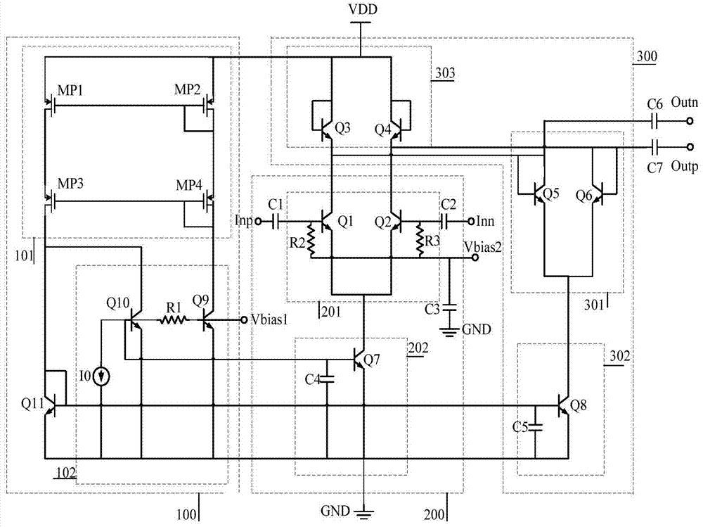
[0034] figure 1 is a circuit diagram of a variable gain amplifier according to an exemplary embodiment of the present invention.

[0035] refer to figure 1, the variable gain amplifier according to an exemplary embodiment of the present invention may include a differential cascode variable transconductance amplifier unit 200 , a differential variable load impedance unit 300 and a gain control unit 100 . The differential common-emitter variable transconductance amplifier unit 200 converts the differential input signal into a differential current signal; the differential variable load impedance unit 300 converts the above-mentioned differential current signal into a differential voltage signal for output; the gain control unit 100 is the above-mentioned The differential common emitter variable tra...


PUM


Abstract

The invention discloses a dB linear ultra-wideband variable gain amplifier. The variable gain amplifier is formed by a variable transconductance amplifier unit, a variable load impedance unit, and a gain control unit, the variable transconductance amplifier unit converts input voltage signals to current signals, the current signals are converted to voltage signals for output via the variable load impedance unit, the variable transconductance amplifier unit and the variable load impedance unit are biased via a tail current source , the current value of the tail current source is controlled via the gain control unit, and transconductance of the variable transconductance amplifier unit and the variable load impedance unit can be adjusted via the gain control unit. The gain is determined by the transconductance ratio between the variable transconductance amplifier unit and the variable load impedance unit, and the gain control unit suitably adjusts the transconductance so that dB linear control characteristics can be obtained.

Description

technical field [0001] The invention relates to a variable gain amplifier, in particular to a dB linear variable gain amplifier with a large working bandwidth. Background technique [0002] A variable gain amplifier is one of the core components in the front end of an RF transceiver. Although the signal strength in the channel between the transmitter and the receiver varies with time, the automatic gain control system in the wireless transceiver can still provide a stable signal strength to the analog-to-digital converter in the baseband. The variable gain amplifier in the automatic gain control system can realize the function of changing its gain, and then provide the required input signal strength for the baseband part. Through the principle of negative feedback, the automatic gain control system can maintain its output signal strength to a predetermined level. In a wireless transceiver, a variable gain amplifier needs to be able to achieve stable gain control and mainta...

Claims


Application Information

Patent Timeline
Patent Type & Authority Patents(China)
IPC IPC(8): H03G3/30H03F1/48H03F3/24
CPCH03F1/3211H03F1/483H03F3/245H03G3/3036
Inventor 李振荣庄奕琪庞瑞刘心彤
Owner XIDIAN UNIV
Why Eureka
Try Eureka