
A Rotary Hearth Furnace Combined Waste Heat Recovery System

A technology of waste heat recovery system and rotary hearth furnace, which is applied in the direction of furnace, waste heat treatment, furnace components, etc., can solve the problems of large investment, poor economy, land occupation and large investment, and achieve low operating cost, convenient source, and avoid secondary The effect of secondary oxidation

Inactive Publication Date: 2017-11-07
JIANGSU PROVINCE METALLURGICAL DESIGN INST
View PDF1 Cites 0 Cited by
  • Summary
  • Abstract
  • Description
  • Claims
  • Application Information

AI Technical Summary

Problems solved by technology

Rotary hearth furnace heat material can be recovered through the horizontal cylinder cooler, but the heat recovery efficiency of the horizontal cylinder cooler is low, and the land occupation and investment are large, the practical effect is poor, and it is difficult to improve the efficiency of the rotary hearth furnace. Target requirements for comprehensive thermal efficiency and reduction of process energy consumption
[0006] Based on the energy recovery of high-temperature flue gas, drawing on the characteristics of CDQ process technology route - using nitrogen as the cooling air medium, the heat exchange of hot material is realized in the vertical counter-current cooler, after dust removal, high-temperature nitrogen is in the Heat exchange in the waste heat boiler, the high-temperature steam generated, the steam turbine is used to generate electricity and recover energy, and the nitrogen is recycled; in order to recover energy from the heat material, although the process route is relatively mature and the degree of waste heat utilization is relatively high, but the two sets of dust removal and purification And the heat exchange system of the waste heat boiler has a large investment, and the input cost of nitrogen production is high, and the economy is poor

Method used


Image

  • A Rotary Hearth Furnace Combined Waste Heat Recovery System
  • A Rotary Hearth Furnace Combined Waste Heat Recovery System
  • A Rotary Hearth Furnace Combined Waste Heat Recovery System

Examples


Embodiment Construction

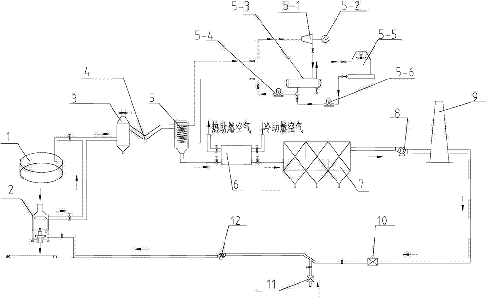
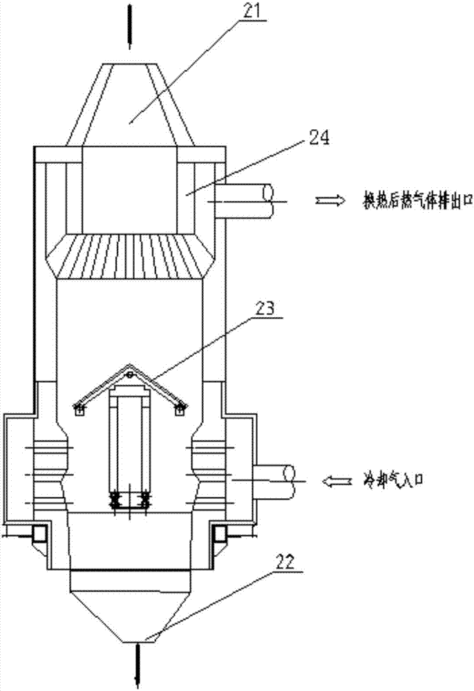
[0024] Such as Figure 1 to Figure 3 As shown, a rotary hearth furnace combined waste heat recovery system of the present invention includes a settling chamber 3 connected to the top end of the rotary hearth furnace 1 and a DRI cooling furnace 2 connected to the bottom end of the rotary hearth furnace 1, and the settling chamber 3 is The pipe 4 is connected with the waste heat boiler 5, the flue gas in the waste heat boiler 5 enters the air heat exchanger 6, the flue gas in the air heat exchanger 6 enters the induced draft fan 8 through the bag filter 7, and the flue gas of the induced draft fan 8 Enter the smoke exhaust chimney 9; the smoke exhaust chimney is connected with the high-pressure blower 12 through a pipeline, and the pipeline between the high-pressure blower 12 and the smoke exhaust chimney 9 is successively provided with an oxygen detection device, an oxygen treatment device 10 and an air supply device 11, and the high-pressure blower 12 The inhaled cooling air e...


PUM


Abstract

The invention discloses a rotary hearth furnace combined waste heat recovery system which comprises a settling chamber connected with the top end of a rotary hearth furnace and a DRI cooling furnace connected with the bottom end of the rotary hearth furnace.The settling chamber is connected with a waste heat boiler through a settling pipe.Smoke in the waste heat boiler enters an air heat exchanger.The smoke in the air heat exchanger enters an induced draft fan through a bag-type dust collector, and the smoke in the induced draft fan enters a smoke exhaust chimney.The smoke exhaust chimney is connected with a high-pressure fan through a pipeline.An oxygen detecting device, an oxygen treating device and an air supplementing device are sequentially arranged on the portion, between the high-pressure fan and the smoke exhaust chimney, of the pipeline.Cooling air sucked by the high-pressure fan enters a cooling air ring channel of a DRI cooling furnace and penetrates through an air channel to exchange heat with hot materials in the DRI cooling furnace, and air after heat exchange enters the settling chamber through the pipeline.Waste heat in the high-temperature smoke generated by the technology of the rotary hearth furnace and waste heat in the hot materials are recovered at the same time, a part of the purified low-temperature smoke can be circulated by itself to be fed into the DRI cooling furnace as cooling media to conduct heat exchange and cool the hot materials, and the operation cost is low.

Description

technical field [0001] The invention relates to a combined waste heat recovery system of a rotary hearth furnace, belonging to the field of mechanical equipment. Background technique [0002] Rotary Hearth Furnace (Rotary Hearth Furnace) process can be used to pre-reduce iron ore, and can also process dust generated by metallurgical plants, and other metallurgical wastes containing iron, chromium, and zinc. The rotary hearth furnace is equipped with carbon pellets or agglomerates as raw materials. Under the high temperature environment of 1250-1350 ℃, the metal oxides in the carbon-containing pellets are quickly reduced by carbon to form metallized pellets. The discharge temperature of the pre-reduction furnace material produced by the rotary hearth furnace process is generally around 1000 ° C, and it is pushed out of the furnace by a screw discharge machine. The rotary hearth furnace process also produces high-temperature flue gas, which takes away ~50% of the heat of the ...

Claims


Application Information

Patent Timeline
Patent Type & Authority Patents(China)
IPC IPC(8): F27D17/00F27D19/00
CPCF27D17/004F27D17/008F27D19/00Y02P10/25Y02P80/15
Inventor 汪朋王敏花黄强
Owner JIANGSU PROVINCE METALLURGICAL DESIGN INST
Learn More