Two-degree-of-freedom heterodyne grating interferometer displacement measurement system and method

A grating interference and displacement measurement technology, applied in measuring devices, instruments, and optical devices, etc., can solve the problems of limited application range, high cost of two-dimensional gratings, and small stroke.

Active Publication Date: 2016-08-03
TSINGHUA UNIV +1
View PDF11 Cites 32 Cited by
  • Summary
  • Abstract
  • Description
  • Claims
  • Application Information

AI Technical Summary

Problems solved by technology

Netherlands ASML company US patent US7,102,729B2 (disclosure date August 4, 2005), US7,483,120B2 (disclosure date November 15, 2007), US7,,940,392B2 (disclosure date December 24, 2009) , Publication No. US2010/0321665A1 (publication date: December 23, 2010) discloses a planar grating measurement system and layout scheme applied to ultra-precision workpiece tables of lithography machines. The measurement system mainly uses a one-dimensional or two-dimensional plane The grating cooperates with the reading head to measure the horizontal large-stroke displacement of the workpiece table, and height sensors such as eddy currents or interferometers are used to measure the displacement in the height direction, but the application of various sensors limits the measurement accuracy of the workpiece table
U.S. Patent Publication No. US2011/0255096A1 (published on October 20, 2011) of ZYGO Corporation of the United States discloses a grating measurement system applied to ultra-precision workpiece tables of lithography machines. The measurement system also uses two-dimensional gratings with specific readings The head realizes the displacement measurement, which can simultaneously measure the horizontal and vertical displacements, but the structure is complicated, an

Method used


Image

  • Two-degree-of-freedom heterodyne grating interferometer displacement measurement system and method
  • Two-degree-of-freedom heterodyne grating interferometer displacement measurement system and method
  • Two-degree-of-freedom heterodyne grating interferometer displacement measurement system and method

Examples


Embodiment Construction

[0055] The structure, principle and specific implementation of the present invention will be further described in detail below in conjunction with the accompanying drawings.

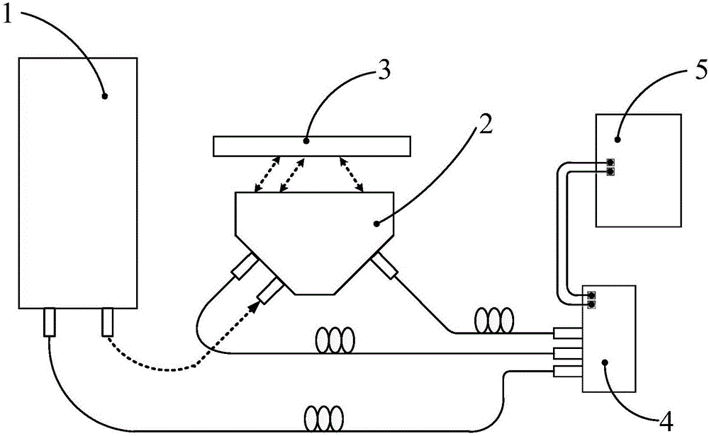
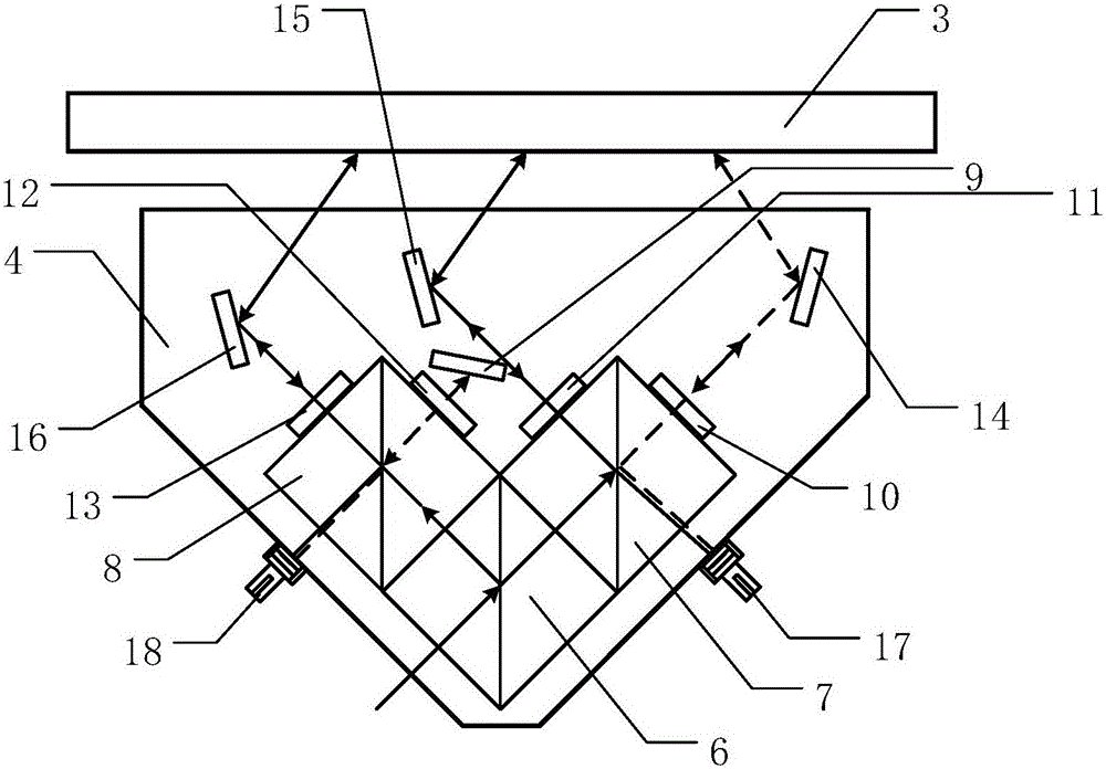
[0056] See figure 1 with figure 2 The two-degree-of-freedom heterodyne grating interferometer displacement measurement system provided by the present invention includes a dual-frequency laser 1, a grating interferometer 2, a measuring grating 3, a receiver 4, and a signal processing unit 5; The base of the groove, the lateral displacement beam splitter prism 6, the first polarization beam splitter prism 7, the second polarization beam splitter prism 8, the reference grating 9, the first quarter wave plate 10, the second quarter wave plate 11, and the third 1 / 4 wave plate 12, fourth 1 / 4 wave plate 13, first mirror 14, second mirror 15, third mirror 16, first fiber coupler 17, and second fiber coupler 18.

[0057] After the dual-frequency laser 1 emits the dual-frequency laser to the lateral displacement bea...


PUM


Abstract

The invention provides a two-degree-of-freedom heterodyne grating interferometer displacement measurement system and method. The system comprises a double-frequency laser device, a grating interferometer, a measuring grating, a receiver and a signal processing unit. The grating interferometer comprises a lateral displacement light splitting prism, a polarization light splitting prism, a 1/4 wave plate, a reflecting mirror and an optical fiber coupler. The method realizes displacement measurement based on grating diffraction, the optical Doppler effect and the optical-beat frequency principle. Laser of the double-frequency laser device is incident to the interferometer and the measuring grating and then optical signals are outputted to the signal processing unit. When the interferometer and the measuring grating perform two-degree-of-freedom linear relative movement, the system can output two linear displacements; the measurement system adopts Littrow incident conditions, a measurement target has large passive movement tolerance and two linear displacements can be measured simultaneously so that precision can reach the nanoscale and higher scale; and the measurement system has advantages of short light path, small size, compact structure, low weight and low requirement for the measuring grating and is suitable for two-degree-of-freedom high-precision long-stroke displacement measurement.

Description

Technical field [0001] The invention relates to a two-degree-of-freedom heterodyne grating interferometer measurement system and method, in particular to the displacement measurement of an ultra-precision workpiece stage, belonging to the technical field of displacement measurement. Background technique [0002] As a typical displacement sensor, the grating measurement system is widely used in many electromechanical equipment. The measurement principle of the grating measurement system is mainly based on the principle of Moiré fringe and the principle of diffraction interference. As a mature displacement sensor, the grating measurement system based on the moiré fringe principle has become the first choice for displacement measurement of many electromechanical equipment due to its many advantages such as long distance measurement, low cost, and easy installation. However, the accuracy is usually on the order of micrometers. For general industrial applications. [0003] Ultra-preci...

Claims


Application Information

Patent Timeline
IPC IPC(8): G01B11/02
CPCG01B11/02
Inventor 朱煜张鸣兰斌王磊杰成荣杨开明鲁森丁思琪徐登峰胡金春尹文生
Owner TSINGHUA UNIV
Why Eureka
Try Eureka