Combined cooling heating and power supply composite energy supply system based on waste heat deep recycling

A technology of combined cooling, heating and power supply and energy supply, which is applied in the direction of heating and cooling combination, machines using waste heat, energy-saving heating/cooling, etc. It can solve the problems of difficulty, restriction and limitation of power grid connection, and increase the adjustment range of heat-to-electricity ratio , Improve the heating energy efficiency, the effect of high heating energy efficiency

Active Publication Date: 2016-08-10
HUAZHONG UNIV OF SCI & TECH
View PDF7 Cites 12 Cited by
  • Summary
  • Abstract
  • Description
  • Claims
  • Application Information

AI Technical Summary

Problems solved by technology

For example, CN20142064744.2 discloses an urban sewage combined cooling, heating and power supply system coupled with multiple renewable energy sources, which can make full use of solar energy, wind energy and geothermal energy, and realize two coupling modes according to changes in the demand side, but this The technology is subject to the conditions of solar and wind energy, so it is subject to greater limitat

Method used


Image

  • Combined cooling heating and power supply composite energy supply system based on waste heat deep recycling
  • Combined cooling heating and power supply composite energy supply system based on waste heat deep recycling
  • Combined cooling heating and power supply composite energy supply system based on waste heat deep recycling

Examples


Embodiment Construction

[0022] In order to make the object, technical solution and advantages of the present invention clearer, the present invention will be further described in detail below in conjunction with the accompanying drawings and embodiments. It should be understood that the specific embodiments described here are only used to explain the present invention, not to limit the present invention. In addition, the technical features involved in the various embodiments of the present invention described below can be combined with each other as long as they do not constitute a conflict with each other.

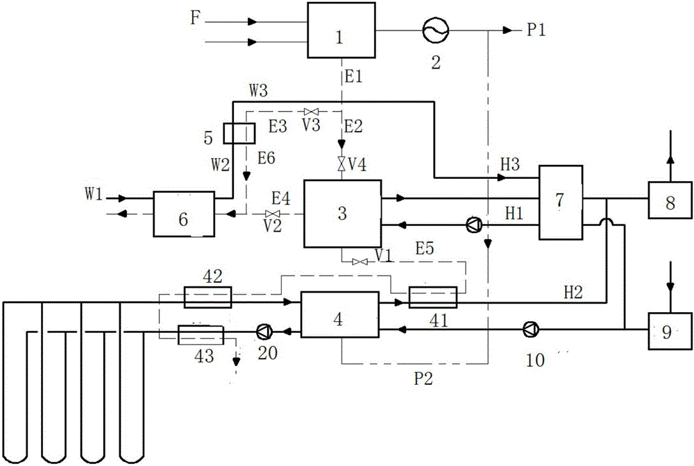
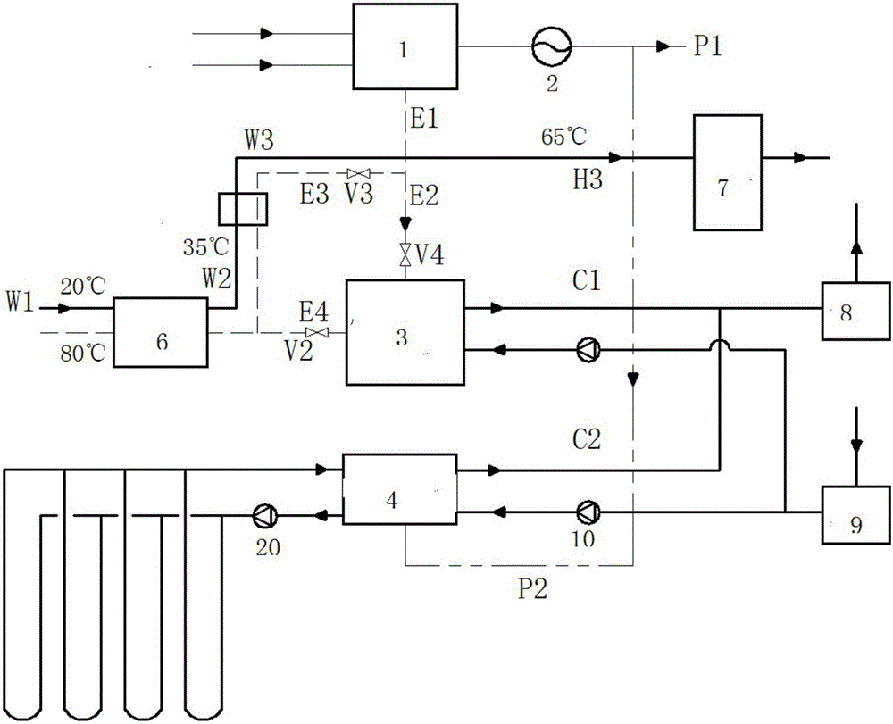
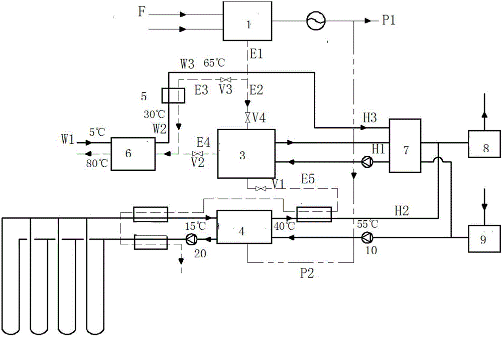
[0023] figure 1 It is a schematic diagram of the overall structure of the composite energy supply system constructed according to the preferred embodiment of the present invention. like figure 1 As shown in , the combined cooling, heating and power supply system mainly includes gas turbine 1, generator unit 2, potassium bromide absorption heat pump unit 3, magnetic levitation heat pump unit 4,...


PUM


Abstract

The invention belongs to the correlated technical field of energy utilization and discloses a combined cooling heating and power supply composite energy supply system based on waste heat deep recycling. The combined cooling heating and power supply composite energy supply system comprises a gas turbine, a generator set, a potassium bromide absorption heat pump unit, a magnetic suspension heat pump unit, a high-temperature flue gas heat exchanger, a flue gas condensing heat exchanger and the like. A flue gas outlet of the gas turbine is divided into two pipelines, the first pipeline is connected with the flue gas type potassium bromide absorption heat pump and drives the flue gas type potassium bromide absorption heat pump to achieve refrigerating and heating, and the second pipeline is connected with the high-temperature flue gas heat exchanger and used for heating tap water preheated through the flue gas condensing heat exchanger to a required temperature. An outlet of the high-temperature flue gas heat exchanger is connected with a flue gas inlet of the flue gas condensing heat exchanger. In addition, one part of electricity generated through the gas turbine is supplied to users, and the other part of the electricity generated through the gas turbine is used for driving the magnetic suspension heat pump unit to conduct refrigerating and heating. According to the combined cooling heating and power supply composite energy supply system based on waste heat deep recycling, flexible composite energy supplying can be carried out, and meanwhile waste heat deep recycling can be achieved; and the combined cooling heating and power supply composite energy supply system has the characteristics of being compact in structure, convenient to control, high in adaptability and the like.

Description

technical field [0001] The invention belongs to the technical field related to energy utilization, and more specifically relates to a composite energy supply system based on the deep recovery of waste heat and combined cooling, heating and power supply. Background technique [0002] Combined cooling, heating and power supply system refers to the operation of gas-fired power generation equipment driven by natural gas as the main fuel. In addition to supplying the electricity demand of users, the waste heat discharged by the system after power generation can provide heat supply and Cooling function. In this way, the primary energy utilization rate of the entire system can be significantly improved, and cascade utilization of energy can be realized; in addition, grid-connected power can be provided for energy complementarity, and the economic benefits and efficiency of the entire system will increase accordingly. [0003] Some combined cooling, heating and power supply schemes...

Claims


Application Information

Patent Timeline
IPC IPC(8): F25B29/00F25B27/02F25B15/06F02C6/00F24H4/02
CPCY02A30/274Y02B30/625F25B29/00F02C6/00F24H4/02F25B15/06F25B27/02
Inventor 胡平放李梦静雷飞朱娜江章宁孙启明邢路严磊李博伦
Owner HUAZHONG UNIV OF SCI & TECH
Why Eureka
Try Eureka