Oil-water separation fiber membrane

A technology of oil-water separation and fiber membrane, which is applied in the direction of filtration separation, fiber treatment, separation methods, etc., can solve the problems of less research on oil pollution, and achieve the effect of good dispersion effect, no agglomeration, and large aspect ratio

Inactive Publication Date: 2016-08-31
NANTONG LOVER APPL
View PDF6 Cites 20 Cited by
  • Summary
  • Abstract
  • Description
  • Claims
  • Application Information

AI Technical Summary

Problems solved by technology

[0008] The sample used for static separation has excellent lipophilicity and can absorb a large amount of oil on the water surface. Ther...

Method used


Image

  • Oil-water separation fiber membrane
  • Oil-water separation fiber membrane
  • Oil-water separation fiber membrane

Examples


Embodiment 1

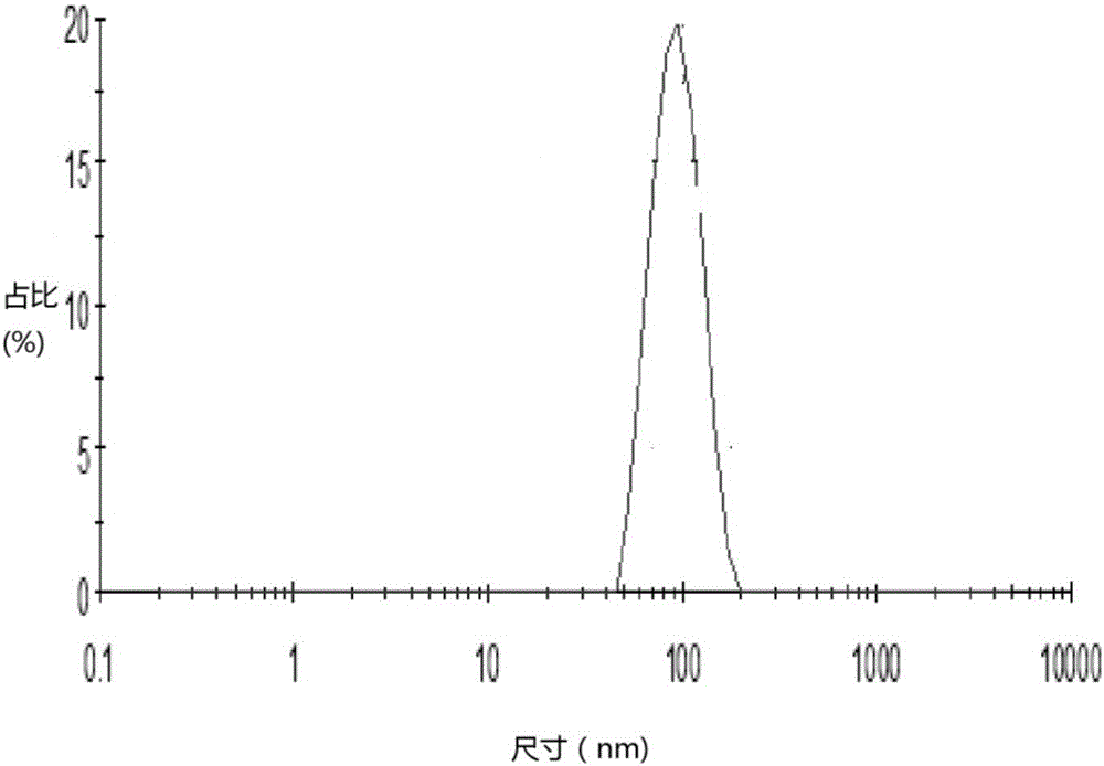
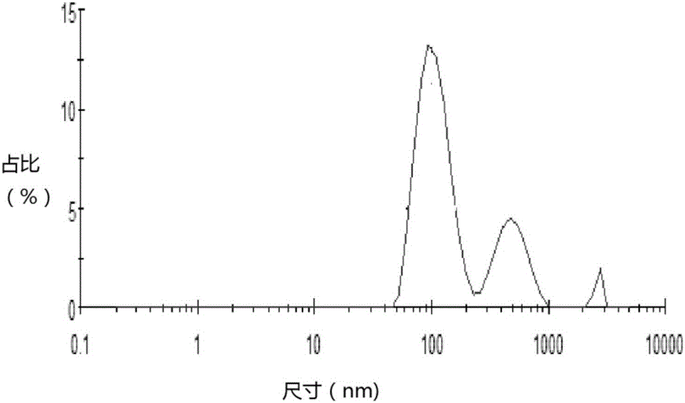
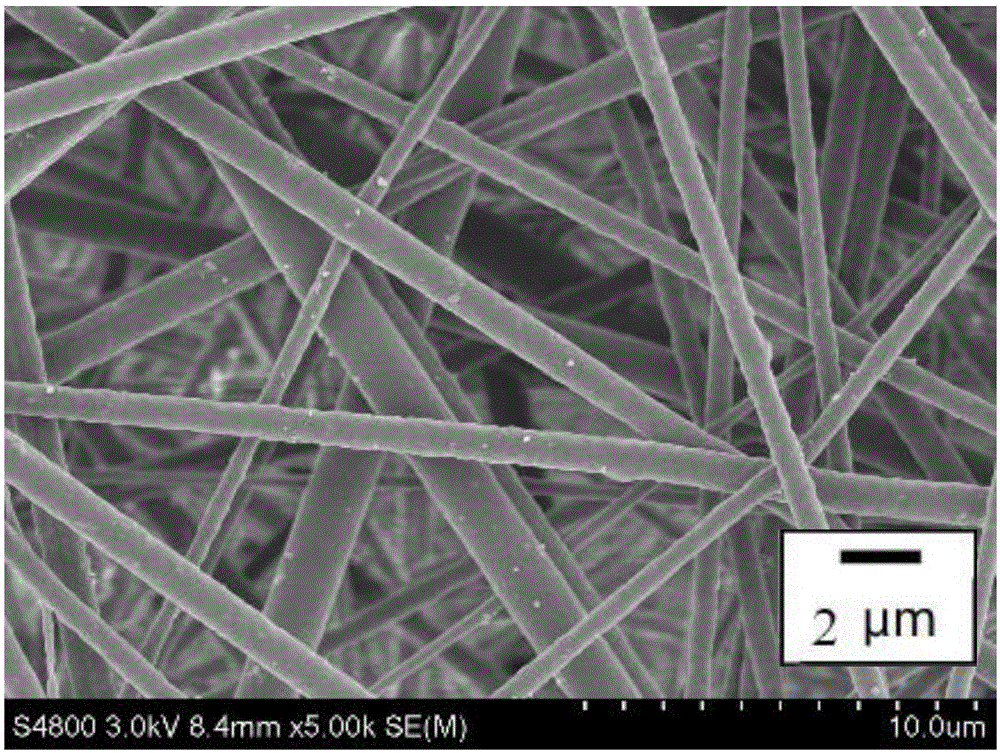
[0036] SiO 2 The nanopowder was placed in DMF, and it was ultrasonically treated with a cell ultrasonic pulverizer for 5 minutes to obtain SiO 2 Dispersion, SiO 2 SiO in dispersion 2 The mass fraction is 0.5%; add PSU particles into the dispersion liquid, and mechanically stir until it is completely dissolved to obtain a uniform and stable spinning solution, in which the PSU mass fraction is 15%; inject the spinning solution into parallel arrangement of multi-nozzle electrospinning machine to prepare PSU / SiO 2 Oil-water separation nanofiber membrane, the spinning process conditions are: spinning voltage 11kv, spinning distance 17cm, needle cylinder traverse distance 11cm, traverse speed 34cm / min, spinning speed 6m / min, spinning liquid flow rate 1ml / h.

[0037] figure 1 It is SiO after crushing by cell ultrasonic pulverizer 2 Diameter distribution diagram, as can be seen from the figure, SiO 2 The particle size distribution is around 100nm, and the distribution range is...

Embodiment 2

[0043] SiO 2 The nanopowder was placed in DMF, and it was ultrasonically treated with a cell ultrasonic pulverizer for 5 minutes to obtain SiO 2 Dispersion, SiO 2 SiO in dispersion 2 The mass fraction is 1%; add PSU particles into the dispersion liquid, and mechanically stir until it is completely dissolved to obtain a uniform and stable spinning solution, in which the PSU mass fraction is 20%; inject the spinning solution into parallel multi-nozzle electrospinning machine to prepare PSU / SiO 2 Oil-water separation nanofiber membrane, the spinning process conditions are: spinning voltage 9kv, spinning distance 14cm, needle cylinder traverse distance 8cm, traverse speed 30cm / min, spinning speed 8m / min, spinning liquid flow rate 2ml / min h.

Embodiment 3

[0045] SiO 2 The nanopowder was placed in DMF, and it was ultrasonically treated with a cell ultrasonic pulverizer for 5 minutes to obtain SiO 2 Dispersion, SiO 2 SiO in dispersion 2 The mass fraction is 1.5%; add PSU particles into the dispersion liquid, and mechanically stir until it is completely dissolved to obtain a uniform and stable spinning solution, in which the PSU mass fraction is 20%; inject the spinning solution into parallel multi-nozzle electrospinning machine to prepare PSU / SiO 2 Oil-water separation nanofiber membrane, the spinning process conditions are: spinning voltage 9kv, spinning distance 14cm, needle cylinder traverse distance 10cm, traverse speed 34cm / min, spinning speed 6m / min, spinning liquid flow rate 1.5ml / h.


PUM


Abstract

The invention relates to an oil-water separation fiber membrane. The oil-water separation fiber membrane is prepared through the following steps that nanosilicon dioxide powder is added into an organic solvent to be smashed so as to obtain silicon dioxide dispersion liquid; polymer particles resistant to acid and base are added into the silicon dioxide dispersion liquid, and stirring is carried out to obtain a spinning solution; the spinning solution is injected into an electrostatic spinning machine for electrostatic spinning, and therefore the oil-water separation fiber membrane is obtained. The oil-water separation fiber membrane has good acid and base resistance, can be used for efficient static oil-water separation, has the ultrahigh specific area and good oil-wet hydrophobicity, has the good oil absorbing effect and the oil-water separation effect, and can be applied to treating oil-water mixed waste water with high acidity and alkalinity.

Description

technical field [0001] The invention relates to the technical field of application of new textile materials, in particular to an oil-water separation fiber membrane. Background technique [0002] Oil is an important source of water pollution. Oily wastewater has a wide range of sources, and many industries that human beings depend on for survival, such as: petrochemical, machinery manufacturing, transportation, leather processing, textile manufacturing, food processing, pharmaceutical production, etc., inevitably produce a large amount of oily wastewater. According to statistics, 5 to 10 million tons of oil are injected into the ocean through various channels every year. The direct discharge of oily wastewater without treatment not only wastes valuable oil resources, but also causes serious damage to the ecological environment. The separation of oil and water is of great significance to oil recovery, water resource reuse and environmental protection. Therefore, with the c...

Claims


Application Information

Patent Timeline
IPC IPC(8): D04H1/4326D04H1/728D01F6/94D01F1/10D01D5/00B01D39/08
CPCD04H1/728B01D39/086D01D5/003D01D5/0092D01F1/10D01F6/94D04H1/4326
Inventor 周小进潘志娟潘世俊洪剑寒胡小明梅德祥石继均
Owner NANTONG LOVER APPL
Why Eureka
Try Eureka