
Device and method for preparation of continuous carbon fiber with carbon nanotubes growing on surface

A carbon nanotube and surface growth technology, which is applied in the fields of carbon fiber, fiber treatment, textiles and papermaking, etc., can solve the problem that carbon nanotubes cannot be modified carbon fiber, and achieve the effects of low cost, continuity and high conversion efficiency

Active Publication Date: 2016-08-31
HARBIN INST OF TECH
View PDF6 Cites 7 Cited by
  • Summary
  • Abstract
  • Description
  • Claims
  • Application Information

AI Technical Summary

Problems solved by technology

[0003] The present invention aims to solve the technical problem that the existing method for preparing carbon nanotubes on the surface of carbon fibers cannot obtain continuous modified carbon fibers, and provides a device and method for preparing continuous carbon fibers with carbon nanotubes grown on the surface

Method used


Image

  • Device and method for preparation of continuous carbon fiber with carbon nanotubes growing on surface
  • Device and method for preparation of continuous carbon fiber with carbon nanotubes growing on surface
  • Device and method for preparation of continuous carbon fiber with carbon nanotubes growing on surface

Examples


specific Embodiment approach 1

[0016] Embodiment 1: The device for preparing continuous carbon fibers with carbon nanotubes grown on the surface of this embodiment,

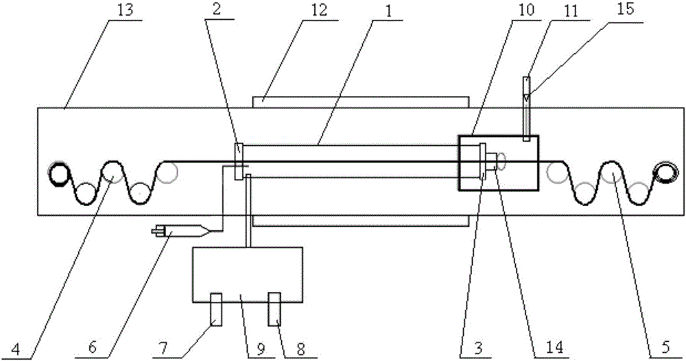
[0017] Including quartz tube 1, head sealing plug 2, tail sealing plug 3, front drafting roller 4, rear drafting roller 5, micro injection pump 6, hydrogen generator 7, argon gas bottle 8, gas mixing device 9, exhaust gas Processing device 10, exhaust pipe 11, heating jacket 12 and sealing chamber 13; Head end sealing plug 2 and tail end sealing plug 3 are all provided with wire holes, and the two ends of quartz tube 1 are respectively sealed with head end sealing plug 2 and The tail end sealing plug 3 is plugged, the tail of the quartz tube 1 is in the exhaust gas treatment device 10, the quartz tube 1, multiple front drafting rollers 4, multiple rear drafting rollers 5 and the exhaust gas treatment device 10 are all arranged in the sealing chamber 13 Inside, the front drafting roller 4 is located in front of the head end sealing plug 2, the ...

specific Embodiment approach 2

[0018] Specific embodiment two: the difference between this embodiment and specific embodiment one is that the device for preparing continuous carbon fibers with carbon nanotubes grown on the surface also includes a gas filter 14 arranged in the tail gas treatment device 10, and the gas filter 14 is connected to the tail gas. On the end sealing plug 3, the others are the same as in the first embodiment.

[0019] The gas filter 14 of this embodiment can remove carbon deposits.

specific Embodiment approach 3

[0020] Embodiment 3: This embodiment differs from Embodiment 1 or Embodiment 2 in that the device for preparing continuous carbon nanotubes on the surface of continuous carbon fibers also includes a one-way valve 15 arranged in the exhaust pipe 11 . Others are the same as in the first or second embodiment.

[0021] The one-way valve 15 in this embodiment can ensure the one-way flow of gas and prevent outside air from entering.


PUM


Abstract

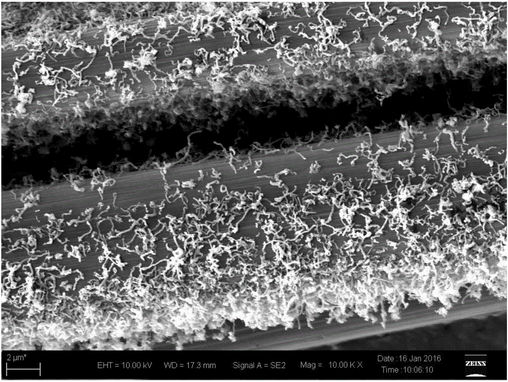
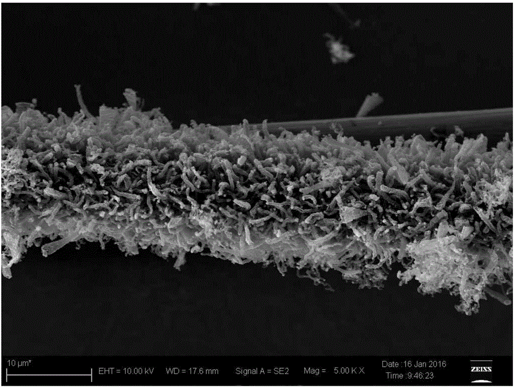
Relating to devices and methods for carbon fiber interfacial modification, the invention provides a device and method for preparation of continuous carbon fiber with carbon nanotubes growing on the surface. The invention aims to solve the problem that continuous modified carbon fiber cannot be obtained through existing modification of carbon fiber with carbon nanotubes. The device comprises a quartz tube, a head-end sealing plug, a tail-end sealing plug, front drawing rollers, back drawing rollers, a micro-injection pump, a hydrogen generator, an argon bottle, a gas mixing apparatus, a tail gas treatment device, an exhaust pipe, a heating jacket and a sealed bin. The micro-injection pump and the gas mixing apparatus are both connected to the quartz tube, and the heating jacket is disposed outside the sealed bin. The method consists of: passing a carbon fiber tow through the front drawing rollers, the back drawing rollers and the quartz tube and conducting tensioning, introducing argon into the quartz tube to perform purification, then introducing the mixed gas of hydrogen and argon into the heated quartz tube, then dissolving ferrocene into a solvent and then introducing the product into the quartz tube, and depositing carbon nanotubes on the surface of moving carbon fiber so as to obtain continuous carbon fiber with carbon nanotubes growing on the surface. And the continuous carbon fiber with carbon nanotubes growing on the surface can be used as a reinforcement in composite materials.

Description

technical field [0001] The invention belongs to a device and a method for modifying a carbon fiber interface. Background technique [0002] As a high-performance fiber, carbon fiber has a series of excellent properties such as high specific strength, high specific modulus, fatigue resistance, creep resistance, small thermal expansion coefficient and low friction coefficient, making it one of the most important reinforcing materials in recent years. , and are widely used in many fields. However, due to the graphite random layer structure on the surface of the carbon fiber, the surface is inert, the surface energy is low, and the active functional groups are few, so there are many defects in the bonding interface with the matrix, and the interface bonding strength is low. The interlayer shear strength of the composite material Low. In order to improve the interfacial strength of carbon fibers, carbon nanotubes were prepared on the surface of short fibers by chemical vapor de...

Claims


Application Information

Patent Timeline
Patent Type & Authority Applications(China)
IPC IPC(8): D06M11/74D06M101/40
CPCD06M11/74D06M2101/40
Inventor 姜再兴董继东贺金梅黄玉东贾储源张广玉
Owner HARBIN INST OF TECH
Learn More