Deposition forming manufacturing method of parts and molds
A technology of forming processing and manufacturing method, which is applied in the field of fusion deposition forming processing and manufacturing of parts and molds, can solve the problems that the structure performance and stability cannot meet the requirements, and achieve the effects of low cost, improved metallurgical quality, and a wide range of materials
- Summary
- Abstract
- Description
- Claims
- Application Information
AI Technical Summary
Problems solved by technology
Method used
Image
Examples
Embodiment 1
[0046] In this example, a gas-shielded arc welding torch is used to prepare a die-casting mold with complex cooling channels and thin-walled and thick-walled shapes. The electric current is 250A, and its specific preparation method is as follows:
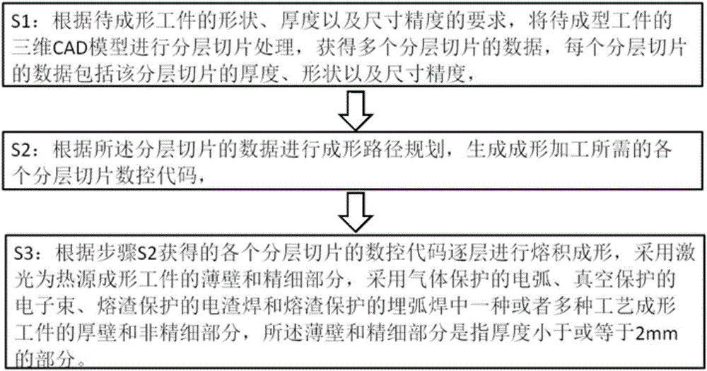
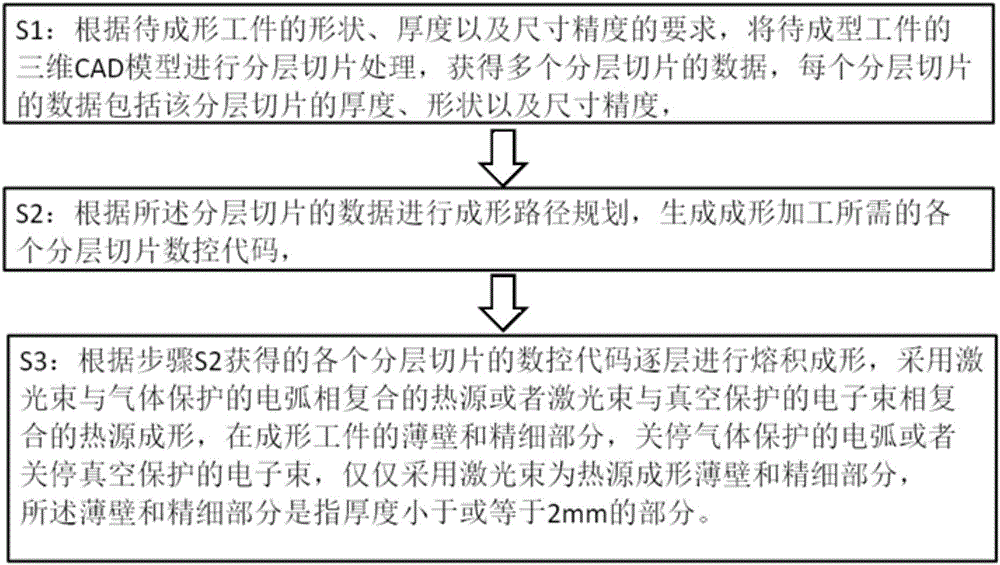
[0047] S1: According to the requirements of the shape, thickness and dimensional accuracy of the mold to be formed, the 3D CAD model of the workpiece to be formed is subjected to layered slice processing to obtain the data of the layered slice, and the data of each layered slice includes the layered slice Thickness, shape and dimensional accuracy,
[0048] S2: Carry out forming path planning according to the data of the layered slices, generate NC codes for each layered slice required for forming processing,
[0049] S3: Perform fusion deposition layer by layer according to the numerical control codes of each layered slice obtained in step S2. Specifically, on the substrate, according to the digital forming processing path obtaine...
Embodiment 2
[0054] A gas-shielded arc welding torch is used, and the welding current is 250A. According to the performance requirements of the injection mold cavity with complex fine ribs and cooling flow channels to be fabricated by deposition, stainless steel wire is used as raw material for forming.
[0055] S1: According to the requirements of the shape, thickness and dimensional accuracy of the mold to be formed, the 3D CAD model of the workpiece to be formed is subjected to layered slice processing to obtain the data of the layered slice, and the data of each layered slice includes the layered slice Thickness, shape and dimensional accuracy,
[0056] S2: Carry out forming path planning according to the data of the layered slices, generate NC codes for each layered slice required for forming processing,
[0057] S3: Perform fusion deposition layer by layer according to the numerical control codes of each layered slice obtained in step S2. Specifically, on the substrate, according to...
Embodiment 4
[0059] The electroslag welding method is adopted, the welding voltage is 25V, and according to the performance requirements of the mold cavity to be manufactured by deposition, low-alloy plates are used, and the digital forming process path obtained from the three-dimensional CAD model of the mold is used on the substrate layer by layer. deposition forming. Specifically:
[0060] S1: According to the requirements of the shape, thickness and dimensional accuracy of the mold to be formed, the 3D CAD model of the workpiece to be formed is subjected to layered slice processing to obtain the data of the layered slice, and the data of each layered slice includes the layered slice Thickness, shape and dimensional accuracy,
[0061] S2: Carry out forming path planning according to the data of the layered slices, generate NC codes for each layered slice required for forming processing,
[0062] S3: Perform fusion deposition layer by layer according to the numerical control codes of e...
PUM
| Property | Measurement | Unit |
|---|---|---|
| thickness | aaaaa | aaaaa |
Abstract
Description
Claims
Application Information
 - R&D
- Intellectual Property
- Life Sciences
- Materials
- Tech Scout
- Unparalleled Data Quality
- Higher Quality Content
- 60% Fewer Hallucinations
Browse by: Latest US Patents, China's latest patents, Technical Efficacy Thesaurus, Application Domain, Technology Topic, Popular Technical Reports.
© 2025 PatSnap. All rights reserved.Legal|Privacy policy|Modern Slavery Act Transparency Statement|Sitemap|About US| Contact US: help@patsnap.com


