In-situ surface-enhanced Raman spectroscopy system and application thereof

A surface-enhanced Raman and spectroscopic system technology, applied in the field of spectroelectrochemistry, can solve the problems of single surface-enhanced Raman substrate and inability to modify electrodes, and achieve good photocatalytic performance, good light transmission performance, and broad application prospects.

Inactive Publication Date: 2016-09-21
TONGJI UNIV
View PDF5 Cites 5 Cited by
  • Summary
  • Abstract
  • Description
  • Claims
  • Application Information

AI Technical Summary

Problems solved by technology

The prepared three-electrode chip electrode has a single surface-enhanced Raman substrate, and the electrode cannot be modified according to the special needs of the experiment.

Method used


Image

  • In-situ surface-enhanced Raman spectroscopy system and application thereof
  • In-situ surface-enhanced Raman spectroscopy system and application thereof
  • In-situ surface-enhanced Raman spectroscopy system and application thereof

Examples


Embodiment 1

[0036] 1) TiO 2 Preparation of NTs / Ti electrode: Grind the titanium plate and sonicate for five minutes according to water, ethanol, and water respectively, at V(HCl):V(H 2 (O)=1:1 etch for 10min until the solution turns purple. then in NH 4 F is oxidized at a constant potential (30V) in an ethylene glycol solution, and after cleaning, it is heated in a tube furnace at 500°C for 3 hours to obtain TiO 2 array of nanotubes.

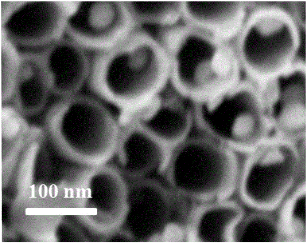
[0037] 2) Preparation of AuNPs / TiO by cyclic voltammetry 2 On NTs / Ti electrode: Potential -0.9V~0V, Pt wire as counter electrode, saturated calomel electrode as reference electrode, AuNPs / TiO 2 NTs / Ti is the working electrode, at 2mmol L -1 HAuCl 4 and 0.1mol L -1 Preparation of AuNPs / TiO by Cycling Different Numbers of Cycles in KCl Solution 2 NTs / Ti electrode, the final cycle of 15 cycles can get the electrode with good photocatalytic performance and surface-enhanced Raman performance. The scanning electron microscope picture is as follows figur...

Embodiment 2

[0040] Prepare AuNPs / TiO in Example 1 2 NTs / Ti electrode, in-situ photocatalytic degradation of organic pollutant p-nitroaniline on the electrode surface: Take 2mL containing 0.1mol L -1 Na 2 SO 4 Electrolyte, the concentration is 10 -4 mol L -1 The aqueous solution of p-nitroaniline is injected into the electrolytic cell through the reference adapter. Using Pt wire as the counter electrode, AuNPs / TiO 2 The NTs / Ti electrode is used as the anode, and the Ag / AgCl electrode is used as the reference electrode. The effective photoanode area is 4.5cm 2 , adjust the Raman spectrometer to focus on the electrode surface. Under the irradiation of ultraviolet light with a wavelength of 365nm and a power of 5W, a bias voltage of 0.6V was applied to continuously measure the surface-enhanced Raman spectrum of the degradation process of p-nitroaniline, and analyze its presence in AuNPs / TiO 2 Photocatalytic degradation process on NTs / Ti electrode surface. From Figure 4 It can be se...

Embodiment 3

[0042] Take 2mL concentration as 10 -4 mol L -1 The p-nitroaniline solution is injected into the electrolytic cell through the reference adapter. Using Pt wire as the counter electrode, AuNPs / TiO 2 The NTs / Ti electrode is used as the anode, and the Ag / AgCl electrode is used as the reference electrode. The effective photoanode area is 4.5cm 2 , adjust the Raman spectrometer to focus on the electrode surface. Under the irradiation of ultraviolet light with a wavelength of 365nm and a power of 5W, the surface-enhanced Raman spectrum of the degradation process of p-nitroaniline was continuously measured, and its concentration in AuNPs / TiO 2 Photocatalytic degradation process on NTs / Ti electrode surface.


PUM

PropertyMeasurementUnit
wavelengthaaaaaaaaaa

Abstract

The present invention relates to an in-situ surface-enhanced Raman spectroscopy system and the application thereof. The system comprises a Pt wire served as a counter electrode, an electrolytic cell body internally provided with a disc space for placing a working electrode and containing a solution, the working electrode disposed in the disc space, a reference switching port in communication with the electrolytic cell body and used for placing a reference electrode, a Pt wire lead connected with the working electrode, an electrolytic cell lid covered above the electrolytic cell body, and an electrolytic cell base used for fixing the working electrode and the electrolytic cell body. The electrolytic cell base is connected with the lower part of the electrolytic cell body, so that the working electrode and the counter electrode are in contact with each other. Compared with the prior art, the system is rapid in detection, low in cost and simple in preparation. Based on the system, the degradation process of p-nitro aniline as an organic pollutant is studied at the molecular level. Therefore, the in-situ rapid detection of intermediate products during the degradation process of p-nitro aniline as the organic pollutant is enabled.

Description

technical field [0001] The invention relates to the technical field of spectroelectrochemistry, in particular to an in-situ surface-enhanced Raman spectroscopy system and its application. Background technique [0002] p-Nitroaniline (p-NA) is an aniline derivative, often used as a precursor or intermediate in the synthesis of organic compounds, and has a wide range of applications in dye manufacturing, pharmaceutical and pesticide industries. At the same time, it itself is a highly toxic pollutant with a strong carcinogenic effect, causing serious impact and damage to the ecological environment, human life and water plants. Therefore, to degrade it and study its degradation mechanism is of great significance to environmental protection and human health. [0003] At present, the degradation methods of environmental organic pollutants mainly include photocatalysis, biological treatment, chemical oxidation, and advanced oxidation, etc., and photoelectric catalysis has a good e...

Claims


Application Information

Patent Timeline
Patent Type & Authority Applications(China)
IPC IPC(8): G01N21/65
CPCG01N21/658
Inventor 曹同成张子玲赵国华
Owner TONGJI UNIV
Why Eureka
Try Eureka