Fe@C@g-C3N4 nanometer composite and preparation method and application thereof

A nanocomposite, g-c3n4 technology, applied in nanotechnology, nanotechnology, nanotechnology for materials and surface science, etc., can solve the problems that nanocomposite microwave absorbing materials have not been reported, and achieve excellent microwave absorption Ability, preparation process conditions are simple, easy to control the effect

Active Publication Date: 2016-09-28
ANHUI UNIVERSITY OF TECHNOLOGY
View PDF10 Cites 5 Cited by
  • Summary
  • Abstract
  • Description
  • Claims
  • Application Information

AI Technical Summary

Problems solved by technology

After retrieval, Fe@C@g-C 3 N 4 Nanocomposite mi

Method used


Image

  • Fe@C@g-C3N4 nanometer composite and preparation method and application thereof
  • Fe@C@g-C3N4 nanometer composite and preparation method and application thereof
  • Fe@C@g-C3N4 nanometer composite and preparation method and application thereof

Examples


Embodiment 1

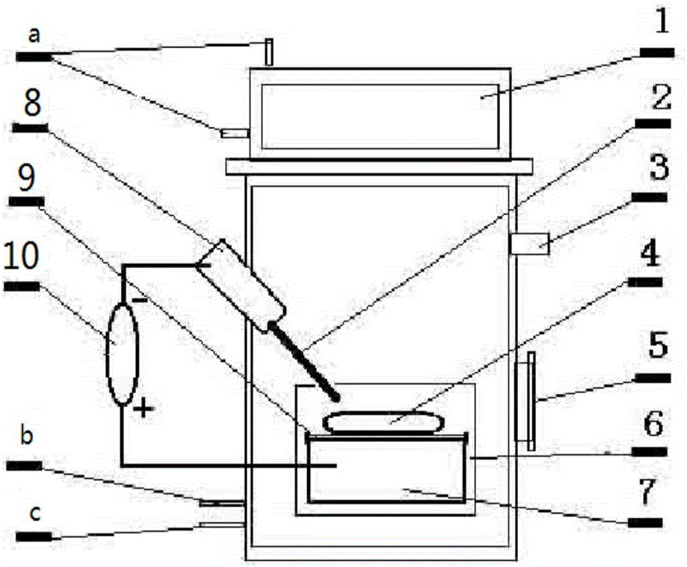
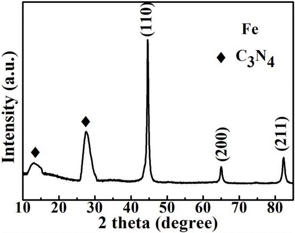
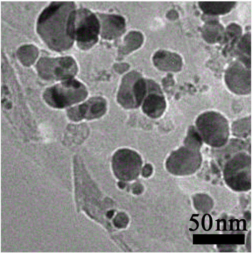
[0032] Will figure 1 The upper cover 1 of the shown device is opened, and graphite is used as the cathode 2 to fix it on the chuck 8. The anode target 4 consumed is a block pressed from pure iron powder and melamine powder (mass ratio 90:10). On the copper anode 7 passing through the cooling water, between the copper anode 7 and the anode target 4 is a graphite crucible 9 . A distance of 30 mm is maintained between the cathode 2 and the anode target 4 . Cover the upper cover 1 of the device, pass cooling water a, and after the whole working chamber is evacuated through the valve 3, argon gas b and methane gas c are introduced, the partial pressure of argon gas is 0.5MPa, and the partial pressure of methane gas is 0.3MPa , connect the DC pulsating power supply 10, the voltage is 40V, adjust the working current and voltage to keep relatively stable during the arc discharge process, and Fe@C@g-C 3 N 4 nanocomposites. The microstructure of the nanocomposite is Fe@C core-shell ...

Embodiment 2

[0034] Will figure 1The upper cover 1 of the device shown is opened, and graphite is used as the cathode 2 to fix it on the chuck 8. The anode target 4 consumed is a block pressed from pure iron powder and melamine powder (mass ratio 70:30). On the copper anode 7 passing through the cooling water, between the copper anode 7 and the anode target 4 is a graphite crucible 9 . A distance of 30 mm is maintained between the cathode 2 and the anode target 4 . Cover the upper cover 1 of the device, pass cooling water a, and after the whole working chamber is evacuated through the valve 3, argon gas b and methane gas c are introduced, the partial pressure of argon gas is 0.5MPa, and the partial pressure of methane gas is 0.3MPa , connect the DC pulsating power supply 10, the voltage is 10V, adjust the working current and voltage to keep relatively stable during the arc discharge process, and obtain Fe@C@g-C 3 N 4 nanocomposites. The microstructure of the nanocomposite is Fe@C core-...

Embodiment 3

[0036] Will figure 1 The upper cover 1 of the shown device is opened, and graphite is used as the cathode 2 to fix it on the chuck 8. The anode target 4 consumed is a block pressed from pure iron powder and melamine powder (mass ratio 90:10). On the copper anode 7 passing through the cooling water, between the copper anode 7 and the anode target 4 is a graphite crucible 9 . A distance of 2 mm is maintained between the cathode 2 and the anode target 4 . Cover the upper cover 1 of the device, pass cooling water a, and after the whole working chamber is evacuated through the valve 3, argon gas b and methane gas c are introduced, the partial pressure of argon gas is 0.5MPa, and the partial pressure of methane gas is 0.3MPa , connect the DC pulsating power supply 10, the voltage is 20V, adjust the working current and voltage to keep relatively stable during the arc discharge process, and obtain Fe@C@g-C 3 N 4 nanocomposites. The microstructure of the nanocomposite is Fe@C core-...


PUM


Abstract

The invention discloses a Fe@C@g-C3N4 nanometer composite and a preparation method and application thereof, and belongs to the technical field of preparation of nanometer materials. A microscope structure of the nanometer composite material is a Fe@C core shell structure nanocapsule embedded in a g-C3N4 nanometer piece. Iron powder and melamine powder are pressed to a block as an anode target material according to a certain atomic percentage by a plasma arc discharge method; graphite serves as a cathode material; argon and methane serve as working gas; a certain distance is kept between a cathode graphite electrode and an anode iron-melamine powder block; and the arc discharge is performed between an anode and a cathode to obtain the Fe@C@g-C3N4 nanometer composite. A wave absorbing material prepared by the nanometer composite is excellent in microwave absorbing performance in 2-18 GHz range. The Fe@C@g-C3N4 nanometer composite is simple in preparation process, free of after-treatment procedures, low in cost and easy to realize industrial production.

Description

technical field [0001] The invention belongs to the technical field of material preparation, in particular to a Fe@C@g-C 3 N 4 Nanocomposite microwave absorbing material and preparation method thereof. Background technique [0002] With the rapid development of modern science and technology, especially the electronic industry technology, the impact of electromagnetic wave radiation on the environment is increasing. After noise pollution, air pollution, and water pollution, electromagnetic wave pollution has become the fourth largest threat to the ecological environment and human health. public nuisance. Electromagnetic fields transmit energy in the form of electromagnetic waves. Usually, only by using electromagnetic wave absorbing materials to convert electromagnetic wave energy into heat or other forms of energy can electromagnetic pollution be effectively removed. In addition, absorbing materials are also widely used in military technology, such as electronic counterme...

Claims


Application Information

Patent Timeline
IPC IPC(8): B22F1/02B22F9/14B82Y30/00B82Y40/00
CPCB82Y30/00B82Y40/00B22F9/14B22F1/054B22F1/16
Inventor 刘先国崔彩云陈浩孙玉萍
Owner ANHUI UNIVERSITY OF TECHNOLOGY
Why Eureka
Try Eureka