Optical fiber sensing probe for detecting gas and liquid
A technology for optical fiber sensing probes and gas detection, which is applied in optics, light guides, and measuring devices. It can solve the problems of complex system structure, increased instrument volume, difficulty in utilizing the lightness and high integration of optical fiber sensors, and achieves a simple and light structure. , The effect of high signal stability
- Summary
- Abstract
- Description
- Claims
- Application Information
AI Technical Summary
Problems solved by technology
Method used
Image
Examples
Embodiment example 1
[0018] Implementation case 1: Gas and liquid optical fiber sensor combined with Y-type optical fiber
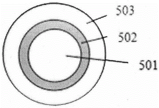
[0019] In this example, the special optical fiber constituting the gas and liquid optical fiber sensing probe 5 is described by taking a capillary optical fiber with a micro-hole structure as an example. Capillary fiber structure such as figure 1 As shown, 501 is a capillary fiber air cavity, 502 is a capillary fiber ring core, and 503 is a capillary fiber cladding. The refractive index of the core 502 of the capillary fiber is higher than the refractive index of the cladding 503. Using the principle of total reflection, the capillary fiber can confine the incident light beam within the numerical aperture in the annular core 502 for transmission.
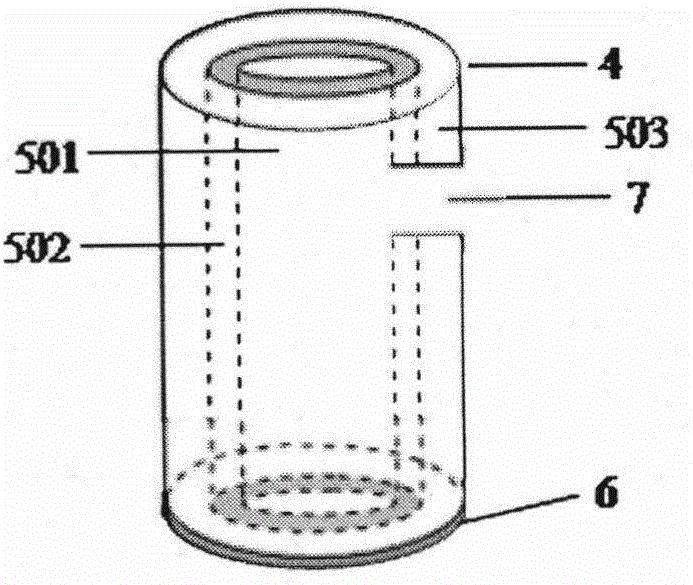
[0020] The manufacturing method of a gas and liquid optical fiber sensing probe in the present invention is as follows figure 2 As shown, one end of the capillary fiber is the light incident end 4, and the other end is formed by chemic...
Embodiment example 2
[0022] Implementation case 2: Gas and liquid optical fiber sensor combined with optical loop device
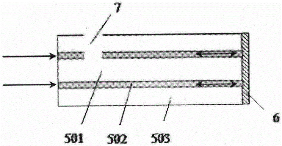
[0023] In this example, the special optical fiber constituting the gas and liquid optical fiber sensing probe 5 is still used such as figure 2 As shown in the capillary fiber, the manufacturing method of the sensing probe is as described in Case 1, and the side sectional view is as image 3 Shown.
[0024] Figure 5 The application of the present invention is shown. In this example, a gas or liquid optical fiber sensor probe can be combined with the optical loop device 3 to form a gas or liquid optical fiber sensor. Combined with the light source 1, the detector 9 can constitute a gas and liquid optical fiber sensing system. The optical circulator 3 has three branches. The 301 port of the optical circulator is connected to the light source 1, and the 302 port of the optical circulator is coupled to the incident end 4 of the optical fiber sensor probe by welding or fusion taper. Th...
Embodiment example 3
[0025] Implementation case 3: Fiber optic sensor probe with sensitive layer modified on the inner surface of the microchannel
[0026] In this example, the special optical fiber constituting the gas and liquid optical fiber sensing probe 5 is still used such as figure 2 The capillary fiber shown. The manufacturing method of the sensing probe is as follows Image 6 As shown, one end of the capillary fiber is used as the light incident end 4, and the other end is coated with a reflective film 6 as the reflection end. A microhole 7 is opened near the light incident end 4, and the microhole 7 penetrates into the capillary fiber to communicate with the central air hole 501. A specific sensitive layer 10 is modified on the inner surface of the capillary fiber ring core 502. The sensitive layer 10 can be a biological probe, a chemically sensitive layer, a fluorescent indicator, or a quantum dot. The sensitive layer 10 should have the following characteristics: its light transmission ch...
PUM
 Abstract
Description
Claims
Application Information
 - R&D
- Intellectual Property
- Life Sciences
- Materials
- Tech Scout
- Unparalleled Data Quality
- Higher Quality Content
- 60% Fewer Hallucinations
Browse by: Latest US Patents, China's latest patents, Technical Efficacy Thesaurus, Application Domain, Technology Topic, Popular Technical Reports.
© 2025 PatSnap. All rights reserved.Legal|Privacy policy|Modern Slavery Act Transparency Statement|Sitemap|About US| Contact US: help@patsnap.com


