Eureka AIR delivers breakthrough ideas for toughest innovation challenges, trusted by R&D personnel around the world.

Biological artificial liver supporting system

A technology of support system and artificial liver, applied in the field of bioartificial liver support system, can solve the problems of decreased cell activity and treatment efficiency, increased blood volume of patients' extracorporeal blood circulation, broken channels, etc., to improve detoxification and biosynthesis efficiency, Reduced risk of immune response, less shedding and breakage

Inactive Publication Date: 2016-11-09
合肥市力维生物科技有限公司
View PDF7 Cites 6 Cited by
  • Summary
  • Abstract
  • Description
  • Claims
  • Application Information

AI Technical Summary

Problems solved by technology

However, there are the following disadvantages: 1. The specific surface area of ​​the hollow fiber is relatively small, and the amount of cells carried by the tube shell is small
2. Suspended cells, or cells attached to microcarriers, cannot achieve a good mixing effect after being added to the outside of the tube, which reduces the use efficiency of the hollow fiber; 3. Whether it is suspended cells or cells attached to microcarriers, In the absence of stirring or shaking, cell accumulation will occur, resulting in insufficient oxygen uptake rate and nutrient deficiency, resulting in reduced cell activity and therapeutic efficiency
However, whether it is fixed bed or fluidized bed technology, the following problems may occur in clinical application: 1. Some carriers of the Cytodex series contain toxic diethylaminoethanol (DEAE) components; 2. During the rapid perfusion process, the carrier Or the gel beads will be broken or the channel will be blocked due to the pressure of the rapid liquid circulation; 3. Usually, several reactors need to be connected in series to achieve a sufficient amount of cells for clinical treatment, which increases the blood volume of the patient's extracorporeal blood circulation at the same time, Increased risk during treatment

Method used


Image

  • Biological artificial liver supporting system

Examples


Embodiment Construction

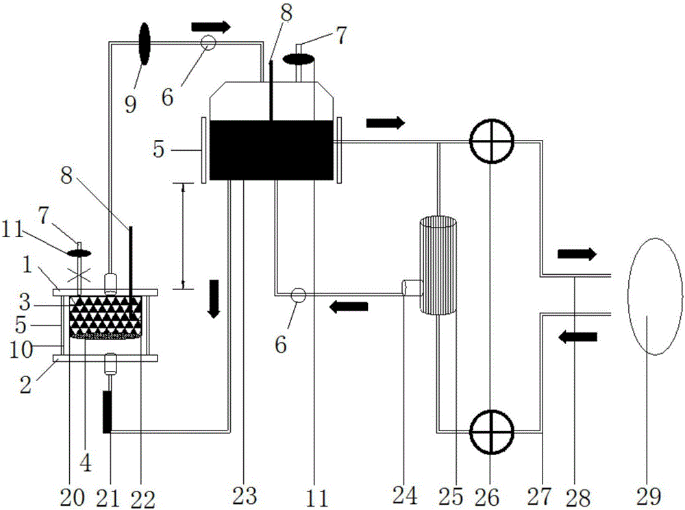
[0030] See attached picture.

[0031] A biological artificial liver support system, including a cell reactor 20, a plasma storage tank 23 and a plasma separator 25; wherein the bottom height of the liquid storage tank is higher than the top height of the cell reactor; the cell reactor includes There is a container 10, the fiber carrier 3 is loaded in the container 10, the filter screen 4 is arranged under the fiber carrier 3 in the container 10, the cell reactor base 2 is installed at the bottom of the container, and the cell reactor top cover 1 is installed on the top of the container 10 The slurry inlet of the plasma separator 25 is connected with the blood output pipeline 27 supplying the patient's arterial blood, and the waste plasma outlet 24 of the plasma separator is connected to the plasma storage tank through the waste plasma input pipeline, and the upper outlet of the plasma separator passes through The blood return pipeline 28 returns to the patient's vein; the bott...


PUM


Abstract

The invention discloses a biological artificial liver supporting system which comprises a cell reactor, a plasma storage tank and a plasma separator. A plasma inlet of the plasma separator is communicated with a blood output pipeline providing blood to arteries of a patient, and a lower-portion outlet of the plasma separator is connected into the plasma storage tank through a pipeline while an upper-portion outlet of the same enables blood to go back into veins of the patients through a blood loop; a bottom plasma outlet of the plasma storage tank is communicated with an inlet of the cell reactor through a plasma incoming pipeline, an outlet of the cell reactor is communicated with a plasma inlet of the plasma storage tank through a plasma return pipeline, and the upper-portion outlet of the plasma storage tank delivers blood back into the veins of the patient through the blood loop. After the biological artificial liver supporting system is used for biological artificial liver treatment for one time, the objective of restoring cell activity can be achieved by adding a fresh culture medium into a carrier and cells in the reactor after cleaning, convenience is brought to being used for treatment of next time, and cost is lowered.

Description

Technical field: [0001] The invention mainly relates to a biological artificial liver support system. Background technique: [0002] Liver failure refers to severe liver damage caused by various factors such as viruses, drugs, and toxins. It is a group of clinical syndromes mainly manifested by coagulation dysfunction, hepatic encephalopathy, ascites, and jaundice. The effect of general conventional medical treatment is not satisfactory, and the case fatality rate is as high as 50%-80%. The emergence of artificial liver treatment technology for liver failure can make some patients with liver failure recover and reduce the mortality rate of patients in general. [0003] Artificial livers are divided into non-biological artificial livers, biological artificial livers and mixed artificial livers. The present invention mainly relates to a biological artificial liver system. The bioartificial liver is an in vitro bioreactor constructed on the basis of artificially cultured hepa...

Claims


Application Information

Patent Timeline
IPC IPC(8): A61M1/18A61M1/36
CPCA61M1/16A61M1/1698A61M1/3601A61M1/3621A61M1/3689A61M2202/0413A61M2205/33A61M2205/3368A61M2205/36A61M2205/75A61M2210/12A61M2202/0021
Inventor 解正刚徐文涛
Owner 合肥市力维生物科技有限公司
Why Eureka
Eureka Blog
Learn More