Sludge treatment method and electrochemical appliance

A treatment method, electrochemical technology, applied in sludge treatment, water/sludge/sewage treatment, dehydration/drying/thickened sludge treatment, etc., can solve limited EPS degradation ability, secondary pollution, and reduce compressibility and other problems, to achieve the effect of deep dehydration, enhanced cracking effect, and enhanced sludge strength

Active Publication Date: 2016-12-14
HUNAN UNIV
View PDF2 Cites 11 Cited by
  • Summary
  • Abstract
  • Description
  • Claims
  • Application Information

AI Technical Summary

Problems solved by technology

Among them, electrochemical treatment is the use of electrochemical methods to degrade refractory organic matter or biotoxic pollutants, which is widely used in wastewater treatment, and has also been applied to sludge treatment in recent years, but its dehydration effect is not good; chemical conditioning Based on Fenton's advanced oxidation technology, it can cause partial oxidation of sludge and improve dehydration performance, but the reaction needs to be carried out at a pH of about 3, which makes subsequent disposal of sludge difficult and easily causes secondary pollution
In addition, by adding an inert filter aid to form a hard skeleton in the sludge, reduce the compressibility of the sludge to improve the filtration performance of the sludge, but it has no obvious effect on improving the existence of bound water in the sludge
The effect of a single sludge conditioning method is limited. Therefore, the use of combined conditioning methods to improve sludge dewatering performance has become a research hotspot in sludge conditioning.
[0006] Luo Haijian and others studied cationic polyacrylamide combined with skeleton particle sawdust to condition urban sludge, and Wang Dongsheng and others studied the combin

Method used


Image

  • Sludge treatment method and electrochemical appliance
  • Sludge treatment method and electrochemical appliance
  • Sludge treatment method and electrochemical appliance

Examples


Embodiment 1

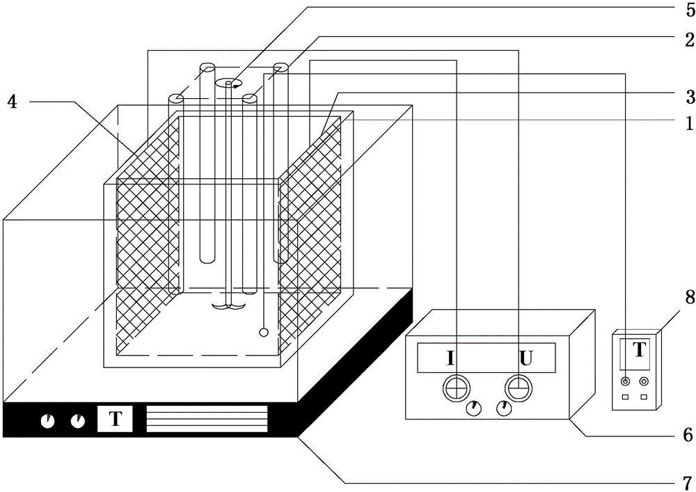
[0047] An electrochemical device, see figure 1 , including a DC power supply 6, an electrolytic cell 1 and an iron rod 2, the electrolytic cell 1 is provided with an anode plate 3 (IrO 2 -RuO 2 / Ti electrode plate) and cathode plate 4 (Ti electrode plate), IrO 2 -RuO 2 The / Ti electrode plate is connected in series with the positive pole of the DC power supply 6; the Ti electrode plate is connected in series with the negative pole of the DC power supply 6 to form a current loop. Iron rod 2 is set in IrO 2 -RuO 2 / Between the Ti electrode plate and the Ti electrode plate.

[0048] Preferably, the distance between the anode plate and the cathode plate is 120mm.

[0049] Preferably, there are four iron rods 2, and the four iron rods 2 are arranged between the anode plate 3 and the cathode plate 4 in a square arrangement, and the distance between each iron rod 2 and the center of the square is 30 mm. The centers of the four iron rods 2 coincide with the centers of the anod...

Embodiment 2

[0054] A method for treating sludge, comprising the steps of:

[0055] (1) The remaining sludge was taken from a sewage plant in Changsha City. After standing for 12 hours, the moisture content of the sludge was 96.0%-96.9%, and the pH of the sludge was 6.80.

[0056] (2) Add sodium persulfate accounting for 11.2% of the dry weight of the sludge to the sludge in step (1) at a stirring rate of 200 r / min, and stir for 5 minutes to obtain a mixture.

[0057] (3) The mixture of step (2) is dropped into the electrolytic cell 1 of the electrochemical device (ie the electrochemical device of embodiment 1), and the submerged depth of four iron rods 2 in the sludge in the electrolytic cell 1 is 30mm.

[0058] (4) Turn on the DC power supply 6 of the electrochemical device and the power supply of the mechanical stirrer 5, and conduct the electrification treatment on the mixture in step (2) for 20 minutes at a stirring rate of 200 r / min and a voltage of 40 V.

[0059] (5) Close the DC p...

Embodiment 3

[0063] A method for treating sludge, comprising the steps of:

[0064] (1) The remaining sludge was taken from a sewage plant in Changsha City. After standing for 12 hours, the moisture content of the sludge was 96.0%-96.9%, and the pH of the sludge was 6.80.

[0065] (2) Add sodium persulfate accounting for 11.2% of the dry weight of the sludge to the sludge in step (1) at a stirring rate of 200 r / min, and stir for 5 minutes to obtain a mixture.

[0066] (3) the mixture of step (2) is dropped into the electrolytic cell 1 of the electrochemical device (i.e. the electrochemical device of embodiment 1), and the submerged depth of four iron rods 2 in the electrolytic cell 1 is 30mm in the sludge .

[0067] (4) Turn on the DC power supply 6 of the electrochemical device and the power supply of the mechanical stirrer 5, and conduct the electrification treatment on the mixture in step (2) for 20 minutes at a stirring rate of 200 r / min and a voltage of 40 V.

[0068] (5) Close the ...


PUM

PropertyMeasurementUnit
Specific resistanceaaaaaaaaaa

Abstract

The invention discloses a sludge treatment method and an electrochemical appliance. The sludge treatment method includes: mixing sodium sulfate with activated sludge to obtain a mixture; placing the mixture into an electrolytic bath, placing an activator between the anode and the cathode of the electrolytic bath and performing electrochemical treatment; continuously adding framework materials in the mixture subjected to the electrochemical treatment prior to stirring to complete treatment of sludge. The electrochemical appliance comprises the electrolytic bath and an iron rod, an anode plate and a cathode plate are arranged in the electrolytic bath, the iron rod is arranged between the anode plate and the cathode plate, the anode plate is of an IrO2-RuO2/Ti electrode plate, and the cathode plate is of a Ti electrode plate. On the basis of electrochemistry-advanced oxidation-framework combined sludge treatment method, sludge dewatering property can be remarkably improved, and the sludge can be odorless after dewatering and stable in property.

Description

technical field [0001] The invention relates to the technical field of sludge treatment, in particular to a sludge treatment method and an electrochemical device. Background technique [0002] With the development of society and urbanization in our country, the increase of sewage treatment volume will inevitably lead to more sludge generation. However, due to various reasons such as technology, economy, environment, society and law, 80% of the sludge in sewage treatment plants in my country cannot be properly treated and disposed of, causing serious secondary pollution, and the bottleneck of sludge disposal technology often lies in sewage. The mud has high moisture content and poor dehydration performance. [0003] The characteristics of high organic matter content, small particle size, strong hydrophilicity, large specific surface area, and strong colloidal structure in sludge make it difficult to dewater. The dewatering performance of sludge has a lot to do with the existi...

Claims


Application Information

Patent Timeline
IPC IPC(8): C02F11/00C02F11/06C02F11/14C02F101/20C02F101/30
CPCC02F11/00C02F11/006C02F11/06C02F11/14C02F2101/20C02F2101/30C02F2305/02
Inventor 袁兴中黎一夫吴志斌冷立健蒋龙波曾光明
Owner HUNAN UNIV
Why Eureka
Try Eureka