A Dual-wavelength Synchronized Pulse Fiber Laser Based on Rare Earth Ion Co-doped Fiber

A fiber laser and synchronous pulse technology, which is applied in the laser field to achieve the effects of narrow pulse width, high integration and improved application efficiency

Active Publication Date: 2019-08-16
SHENZHEN UNIV
View PDF4 Cites 0 Cited by
  • Summary
  • Abstract
  • Description
  • Claims
  • Application Information

AI Technical Summary

Problems solved by technology

At present, the cascading of holmium-doped or erbium-doped fluoride fibers is mainly used to generate dual-wavelength lasers. However, it is difficult to fuse fluoride fibers with silica fibers, which limits the full-fiberization of lasers, and this method currently only achieves wider pulse widths. Dual-wavelength synchronous Q-switched-gain switch pulse output

Method used


Image

  • A Dual-wavelength Synchronized Pulse Fiber Laser Based on Rare Earth Ion Co-doped Fiber
  • A Dual-wavelength Synchronized Pulse Fiber Laser Based on Rare Earth Ion Co-doped Fiber
  • A Dual-wavelength Synchronized Pulse Fiber Laser Based on Rare Earth Ion Co-doped Fiber

Examples


Embodiment 1

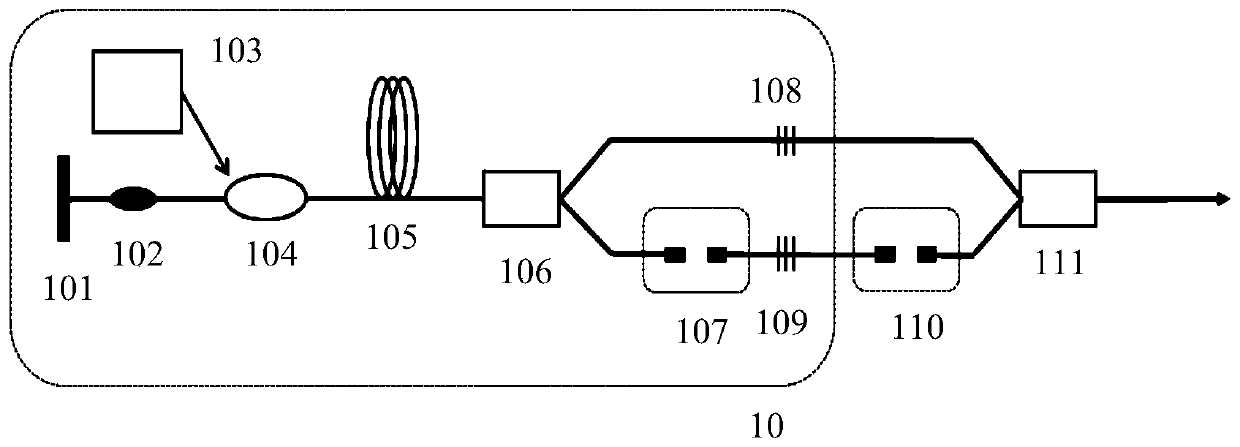
[0028] Embodiment 1, introduces a linear cavity dual-wavelength synchronous pulsed fiber laser based on rare earth ion co-doped fiber, as attached figure 1 Shown:

[0029] Including broadband reflector 101, saturable absorber 102, continuous light LD pump source 103 with pigtail output, pump coupling device 104, rare earth ion co-doped fiber 105, fiber wavelength division multiplexer WDM 1 106. Optical delay line DL 1 107. Fiber Bragg Grating FBG 1 108. Fiber Bragg Grating FBG 2 109, also including optical delay line DL 2 110. Optical fiber wavelength division multiplexer WDM 2 111 and the output terminal.

[0030] Among them, the devices 101-109 constitute the linear cavity dual-wavelength synchronous pulse fiber laser 10, and the devices 110-111 are used to better overlap the two synchronous pulses and output them simultaneously.

[0031] Specifically, the broadband reflector 101, fiber Bragg grating FBG 1 108 and the devices between them form a sensitized ion radiation...

Embodiment 2

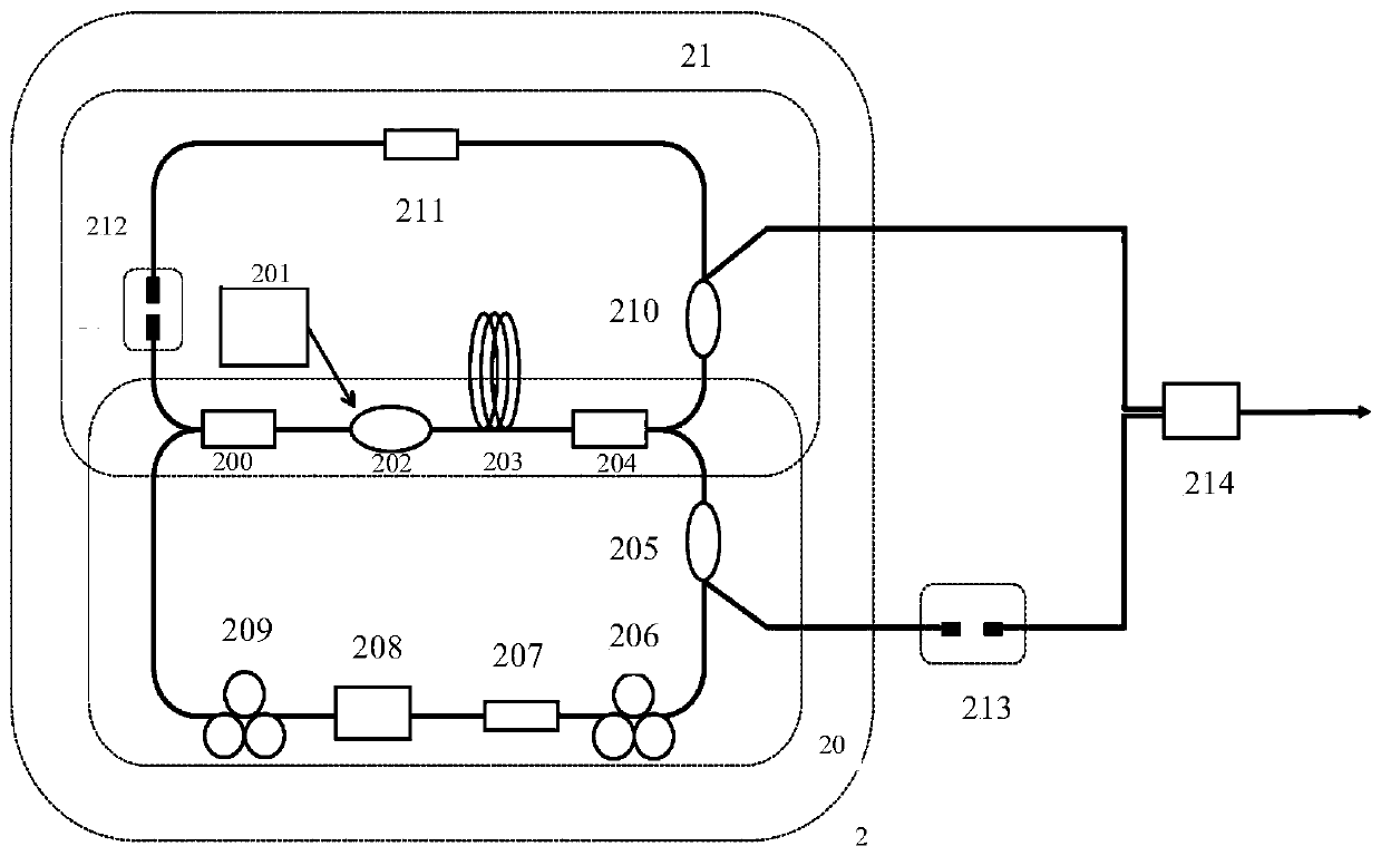
[0037] Embodiment 2, introduces a ring cavity dual-wavelength synchronous pulse fiber laser based on rare earth ion co-doped fiber, as attached figure 2 Shown:

[0038] Including fiber optic wavelength division multiplexer WDM 1 200. CW LD pump source with pigtail output 201, pump coupling device 202, rare earth ion co-doped optical fiber 203, optical fiber wavelength division multiplexer WDM 2 204. Optical fiber coupler OC 1 205. Optical Fiber Polarization Controller PC 1 206. Optical Fiber Polarization Independent Isolator ISO 1 207, fiber optic polarizer 208, fiber optic polarization controller PC 2 209. Optical fiber coupler OC 2 210. Optical Fiber Polarization Independent Isolator ISO 2 211. Optical delay line DL 1 212, also includes optical delay line DL 2 213. Optical fiber wavelength division multiplexer WDM 3 214 and output.

[0039] Among them, the devices 200-209 constitute the sensitized ion radiation laser guiding resonant cavity 20, and the devices 200...


PUM


Abstract

The invention is applicable to the field of laser technology, and provides a dual-wavelength synchronous pulse fiber laser based on a rare earth ion co-doped fiber, including a continuous light LD pump source, a rare earth ion co-doped fiber and a resonant cavity, the continuous light LD pump The source is connected to the resonant cavity, and the rare earth ion co-doped optical fiber is located in the resonant cavity; the sensitized ions in the rare earth ion co-doped optical fiber absorb the pump light, and a laser with a wavelength is generated by the sensitized ion radiation, At the same time, laser light of another wavelength is generated by the sensitized ion radiation in the rare earth ion co-doped optical fiber; the laser light of the sensitized ion radiation is modulated by using a saturable absorber inserted in the laser cavity of the sensitized ion radiation Q or mode-locking makes it generate pulsed laser. This process periodically modulates the gain of the sensitized ion radiation laser and generates synchronous pulsed laser, thereby realizing a dual-wavelength synchronous pulsed fiber laser. The device provided by the invention can be highly integrated and can realize an all-fiber structure.

Description

technical field [0001] The invention belongs to the field of laser technology, in particular to a dual-wavelength synchronous pulse fiber laser based on a rare earth ion co-doped fiber. Background technique [0002] Dual-wavelength lasers have a wide range of applications in the generation of sum frequency / difference frequency, remote sensing, laser ranging, medical purposes, etc., especially dual-wavelength synchronous pulse laser has the advantages of large pulse energy and high peak power synchronous dual-wavelength pulse output , so that it has a better practical application effect. Compared with traditional solid-state lasers, fiber lasers have attracted much attention due to their outstanding advantages such as good heat dissipation, high conversion efficiency, low threshold, good beam quality, and easy integration. At present, there are three main methods of using fiber lasers to realize dual-wavelength synchronous pulse laser output: [0003] 1. Realize dual-wavele...

Claims


Application Information

Patent Timeline
Patent Type & Authority Patents(China)
IPC IPC(8): H01S3/067H01S3/0941
CPCH01S3/06716H01S3/0675H01S3/0941H01S3/082H01S3/094026H01S3/113H01S3/1698H01S3/0809H01S3/1115H01S3/1618H01S3/06791H01S3/10061H01S3/1608H01S3/094061H01S3/108
Inventor 郭春雨刘伟琪阮双琛余军陈业旺罗若恒朱逸怀
Owner SHENZHEN UNIV
Why Eureka
Try Eureka