Sn-Bi base brazing filler metal used for producing crystal silicon heterojunction solar cell electrode

A solar cell and heterojunction technology, applied in circuits, photovoltaic power generation, electrical components, etc., can solve the problems of high battery cost, avoid massive consumption, improve power generation efficiency, and reduce inherent resistance

Inactive Publication Date: 2017-03-15
NANCHANG UNIV
View PDF8 Cites 2 Cited by
  • Summary
  • Abstract
  • Description
  • Claims
  • Application Information

AI Technical Summary

Problems solved by technology

However, the production of crystalline silicon heterojunction solar cells requires a large amount of silver paste electrodes, and the use of silver paste is the main component of the cost of this type of cell, making the cost of this type of cell high

Method used


Image

  • Sn-Bi base brazing filler metal used for producing crystal silicon heterojunction solar cell electrode
  • Sn-Bi base brazing filler metal used for producing crystal silicon heterojunction solar cell electrode

Examples


Embodiment 1

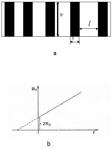
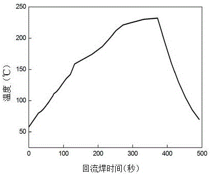
[0016] Melt the Sn-15Bi alloy, cast it at 250°C into a round rod with a diameter of 20mm, cut it into a short column with a height of 10mm, and grind the cross section to make it smooth. The volume resistance was measured by the four-probe method. The volume resistivity of the alloy was measured to be 33 μΩ·cm. The paste made of alloy powder was screen-printed on ITO to form an attached figure 1 The grid line shown in a, wherein the length w of the grid line is 10mm, and the width s is 2mm. to attach figure 2 The temperature regime shown is reflow soldering to obtain metal grid wire electrodes. Measure the total resistance R between any two adjacent grid lines with a multimeter T . make R T ~l linear relationship diagram, as attached figure 1 As shown in b, the contact resistance between the electrode made of the alloy and ITO is 0.50Ω.

Embodiment 2

[0018] Melt the Sn-35Bi-0.5Sb alloy, cast it at 250°C into a round rod with a diameter of 20mm, cut it into a short column with a height of 10mm, and grind the cross section to make it smooth. The volume resistance was measured by the four-probe method. The volume resistivity of the alloy was measured to be 45 μΩ·cm. The paste made of alloy powder was screen-printed on ITO to form an attached figure 1 The grid line shown in a, wherein the length w of the grid line is 10mm, and the width s is 2mm. to attach figure 2 The temperature regime shown is reflow soldering to obtain metal grid wire electrodes. Measure the total resistance R between any two adjacent grid lines with a multimeter T . make R T ~l linear relationship diagram, as attached figure 1 As shown in b, the contact resistance between the electrode made of the alloy and ITO is 0.58Ω.

Embodiment 3

[0020] Melt the Sn-52Bi-0.3Al alloy, cast it at 250°C into a round rod with a diameter of 20mm, cut it into a short column with a height of 10mm, and grind the cross section to make it smooth. The volume resistance was measured by the four-probe method. The volume resistivity of the alloy was measured to be 58 μΩ·cm. The paste made of alloy powder was screen-printed on ITO to form an attached figure 1 The grid line shown in a, wherein the length w of the grid line is 10mm, and the width s is 2mm. to attach figure 2 The temperature regime shown is reflow soldering to obtain metal grid wire electrodes. Measure the total resistance R between any two adjacent grid lines with a multimeter T . make R T ~l linear relationship diagram, as attached figure 1 As shown in b, the contact resistance between the electrode made of the alloy and ITO is 0.65Ω.


PUM


Abstract

The invention discloses a Sn-Bi base brazing filler metal used for producing a crystal silicon heterojunction solar cell electrode belonging to the solar cell material technology field. The components of the Sn-Bi base brazing filler metal are Sn and Bi. The weight percentage content of the Bi is in a range from 5% to 70%, and the residual is Sn. By adopting the above mentioned alloy to replace silver slurry to produce the crystal silicon heterojunction solar cell electrode, great consumption of silver resources is prevented, and costs are greatly reduced, and then the intrinsic resistance of the solar cell is reduced, and therefore great benefits are provided for the further improvement of the power generating efficiency of the battery.

Description

technical field [0001] The invention belongs to the technical field of solar cell materials and relates to a class of alloys suitable for making crystalline silicon heterojunction solar cell electrodes. Background technique [0002] Homojunction polycrystalline silicon and monocrystalline silicon solar cells based on diffusion junction technology are the mainstream products in the current photovoltaic market. Due to the limitations of materials and processes, there is limited room for improvement of conversion efficiency and cost reduction of this type of solar cell. In the development of silicon-based material solar cells, in order to seek higher cell efficiency, researchers proposed a new type of solar cell, crystalline silicon / amorphous silicon (a-Si / c-Si) solar cells, that is, crystalline silicon heterogeneous Mass junction solar cells. After decades of hard work, people have greatly improved crystalline silicon heterojunction solar cells by fine-tuning the structure o...

Claims


Application Information

Patent Timeline
Patent Type & Authority Applications(China)
IPC IPC(8): H01L31/0224
CPCH01L31/022425Y02E10/50
Inventor 魏秀琴黄海宾周浪
Owner NANCHANG UNIV
Why Eureka
Try Eureka