[0002]
Chinese patent CN 204545422 U discloses a "circulating cooling
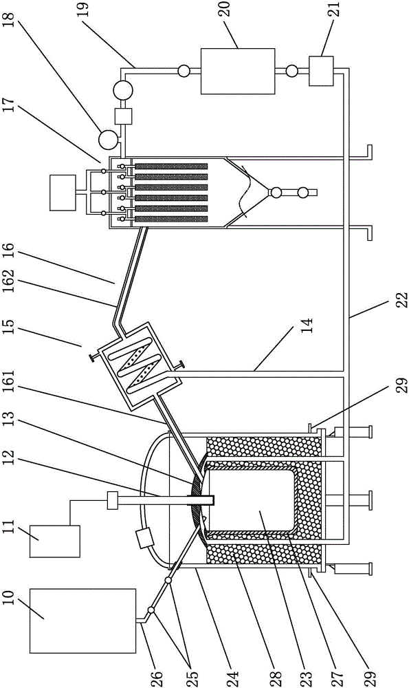
metal particle evaporation production device", which includes a furnace body, a crucible in the furnace body, a plasma spray gun for heating and evaporating metal in the crucible, and a collection of
metal powder produced in the crucible The opening on the upper side of the crucible is provided with a crucible cover, the spray head of the plasma spray gun extends into the inner cavity of the crucible through the crucible cover, and the surface of the crucible cover and the spray head in the crucible is covered with high temperature resistant material The made sheath, heat insulation material is arranged between the furnace body and the crucible, a
vacuum pump and a gas-
solid separator are installed on the air outlet of the collector, and the
cooling pipe drawn from the air outlet of the gas-
solid separator is connected to the exhaust
fan in turn , the
heat exchanger, the gas purification filter and then pass through the furnace body, the
thermal insulation material communicates with the inner cavity of the crucible through the air
inlet channel on the crucible cover, and the
discharge pipe of the storage
barrel and the feed pipe of the collector pass through The furnace body and the crucible lid are in communication with the inner cavity of the crucible. It can be seen from the drawings and instructions that the feed pipe of the collector is a pipe of equal
diameter. When the high-temperature metal vapor passes through the pipeline, it is difficult to cool it quickly, which makes it difficult to control the
diameter of the metal particles below 250nm when the high-temperature metal vapor rapidly grows into metal particles. The demand for metal particles, the metal particles are also called metal
powder[0003]
Chinese patent CN 102951643 B discloses "A Production Method of Nanoscale Spherical
Silicon Powder", which is carried out in a
reaction system composed of a high-temperature
evaporator, a particle controller and a collector connected in sequence, and the particle controller is polycooling Tube, the
tube structure of the polycooling tube includes five
layers, which are
graphite tube,
carbon felt tube,
carbon felt tube, stainless
steel tube, stainless
steel tube from inside to outside. Common sense knows that
graphite tube,
carbon felt tube, carbon felt tube It is a super high temperature resistant material with a high
temperature resistance of up to 1800°C: first, it is proved that the temperature of the gas
silicon in the particle controller is extremely high, so such a high temperature resistant material is needed; second, in the actual production process of CN102951643B, poly One end of the cold pipe (particle controller) is connected to the high-temperature
evaporator, and the other end is connected to the collector. Since the
boiling point of
silicon is 2900°C, the outlet temperature after
silicon vaporization must be about 2900°C. Such a high temperature passes through the so-called polycooling pipe. , the temperature of the circulating water after cooling will not drop too much, causing the silicon particles to collide and grow into large silicon particles very quickly in the polycooling tube. It can be seen from the charts 1 to 3 of the patent examples that the
silicon particle size is D50. The particles are distributed between 500nm and 2700nm, and it is impossible to produce silicon
nanomaterials with D50 (D represents the
diameter of
powder particles, and D50 represents the diameter of the cumulative 50% point, or 50% passing particle size) below 250nm to 20nm; the third is If the flow rate is controlled to reduce the temperature of the silicon particles flowing through the cooling tube and to control the growth rate of the silicon particles in the cooling tube, the production efficiency is very low, which further leads to a high production cost of nano-sized silicon particles; the fourth is to use This method produces submicron-sized
silicon particle materials, and the temperature of the silicon particles cannot drop rapidly when entering the collector, and is generally still at a temperature of 300-450°C. It takes a long time for the silicon to cool down to below 100°C in the collector, and it cannot be continued at all. Circulation and high-efficiency production, if the temperature of the silicon material is at a relatively high temperature, tell the silicon material to be taken out of the collector, and the
oxygen in the air will be natural immediately when the silicon material comes into contact with the air, causing fire in the workshop and waste of materials; the fifth is from the CN 102951643 B patent Tables 1 to 3 of the examples show that the
particle size distribution D50 of silicon particles is above 500-2700nm, and its D50 cannot actually reach the size of silicon particles below 150nm-10nm. Internationally, it is usually referred to as
particle material below 100nm
nanomaterials

