Desulfurization waste water resourceful treatment system and method

A technology for treating system and desulfurization wastewater, applied in energy wastewater treatment, gaseous effluent wastewater treatment, multi-stage water treatment, etc., can solve the problems of adverse effects of evaporation and crystallization on normal operation, affecting system stability and reuse of produced water, etc. To achieve the effect of ensuring normal operation

Inactive Publication Date: 2017-05-31
DATANG INT CHEM TECH RESINST
View PDF6 Cites 5 Cited by
  • Summary
  • Abstract
  • Description
  • Claims
  • Application Information

AI Technical Summary

Problems solved by technology

[0005] In addition, according to the existing project operation experience, affected by the escape of ammonia in the denitrification process, the desulfurization wastewater contains a c...

Method used


Image

  • Desulfurization waste water resourceful treatment system and method

Examples


Embodiment 1

[0049] This embodiment is used to illustrate the desulfurization wastewater resource treatment system and method of the present invention, specifically to treat a kind of desulfurization wastewater generated in the process of SCR denitrification of flue gas and limestone-wet desulfurization in a chemical enterprise's self-provided power plant.

[0050] The main indicators of the wastewater are as follows: pH value 5.0~6.5, conductivity ≤50000μs / cm, chloride ion ≤15000mg / L, ammonia nitrogen ≤400mg / L, COD Cr ≤300mg / L, calcium ≤4000mg / L, magnesium ≤3000mg / L, suspended matter ≤60000mg / L.

[0051] Take the following steps to process:

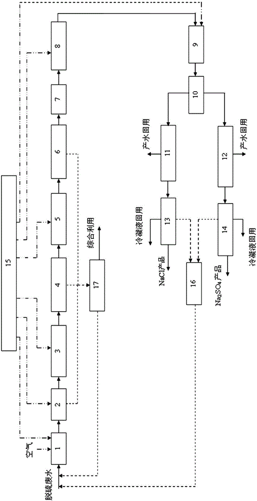
[0052] 1) Discharge the desulfurization wastewater into the buffer pool 1 and pass it into the air for aeration, stirring, and adding sodium hypochlorite, and the effluent COD Cr content dropped below 50mg / L;

[0053] 2) Transfer the effluent from the buffer tank 1 to the pre-sedimentation tank 2, add coagulant 50 mg / L and coagulant aid 0.5 mg / L th...

Embodiment 2

[0068] This embodiment is used to illustrate the desulfurization wastewater resource treatment system and method of the present invention, specifically to treat a kind of desulfurization wastewater generated in the process of power plant flue gas SCR denitrification and limestone-wet desulfurization.

[0069] The main indicators of the wastewater are as follows:

[0070] pH value is 5.0~6.5, conductivity≤30000μs / cm, chloride ion≤10000mg / L, ammonia nitrogen≤80mg / L, COD Cr ≤200mg / L, calcium ≤1000mg / L, magnesium ≤4000mg / L, suspended matter ≤50000mg / L.

[0071] Take the following steps to process:

[0072] 1) Discharge the desulfurization wastewater into the buffer pool 1 and pass it into the air for aeration, stirring, and adding sodium hypochlorite, and the effluent COD Cr content dropped below 50mg / L;

[0073] 2) Transfer the effluent from the buffer tank 1 to the pre-sedimentation tank 2, add coagulant 50 mg / L and coagulant aid 0.5 mg / L through the dosing system 15, the res...


PUM

PropertyMeasurementUnit
Conductivityaaaaaaaaaa

Abstract

The invention provides a desulfurization waste water resourceful treatment system and method. The treatment system comprises a buffer pool 1, a pre-settling tank 2, a first-order reaction flocculating tank 3, a primary clarification concentration tank 4, a second-order reaction flocculation tank 5, a secondary clarification concentration tank 6, a filter 7, a breakpoint chlorination system 8, an intermediate water pool 9, a nanofiltration system 10, a NaCl preconcentration system 11, a Na2SO4 preconcentration system 12, a NaCl evaporation crystallization system 13, a Na2SO4 evaporation crystallization system 14, a dosing system 15, a mother liquor collection tank 16 and a sludge treatment system 17. Compared with the prior art, the method utilizes an ammonia nitrogen removal process to remove ammonia nitrogen in waste water so that long-term and stable operation of an evaporation crystallization device is guaranteed. Through use of membrane separation, concentration and evaporation crystallization processes, salt dividing, recovery and recycle are realized. Through a complete treatment process, various types of impurities are removed step by step and normal operation of various devices and stable operation of the whole treatment are guaranteed.

Description

technical field [0001] The invention belongs to the technical field of industrial wastewater treatment, and in particular relates to a treatment system and method for resource utilization of desulfurization wastewater. Background technique [0002] At present, limestone-gypsum wet flue gas desulfurization technology is mostly used for desulfurization, and the desulfurization wastewater produced has high salt content (30000-60000mg / L), high suspended solid content (above 10000mg / L), high hardness and easy scaling (SO 4 2- Above 4000mg / L, Ca 2+ At 1500~5000mg / L, Mg 2+ At 3000~6000mg / L), highly corrosive (Cl - 5000~20000mg / L and the pH value is acidic), containing a variety of heavy metal ions (mercury, cadmium, chromium, nickel, etc.) and so on. [0003] After the desulfurization wastewater is treated by traditional neutralization, precipitation, flocculation, and clarification processes, it still has the characteristics of high salt content and high corrosion, which is a ...

Claims


Application Information

Patent Timeline
IPC IPC(8): C02F9/10C02F103/18
CPCY02W10/37C02F9/00C02F1/04C02F1/441C02F1/442C02F1/445C02F1/469C02F1/5236C02F1/5245C02F1/54C02F1/56C02F1/66C02F1/76C02F7/00C02F2001/007C02F2001/5218C02F2103/18C02F2301/08
Inventor 李春启牟伟腾岳培恒刘俊峰梅长松刘学武王宝强岳子明王金惠
Owner DATANG INT CHEM TECH RESINST
Why Eureka
Try Eureka