Double dielectric barrier discharge device with catalytic coating for waste gas treatment

A technology of blocking discharge and catalytic coating, which is applied in gas treatment, air quality improvement, chemical instruments and methods, etc. It can solve the problems of large air flow pressure drop loss, low energy utilization rate, and inability to fully utilize transient active substances. Achieve the effect of small airflow pressure drop loss, improve energy efficiency, and inhibit the formation of deposits

Pending Publication Date: 2017-06-09
ZHEJIANG UNIV
View PDF4 Cites 18 Cited by
  • Summary
  • Abstract
  • Description
  • Claims
  • Application Information

AI Technical Summary

Problems solved by technology

In the traditional one-stage plasma catalytic device, the catalyst layer is placed in the plasma discharge area, resulting in a large loss of air flow pressure drop, and deposition will still occur on the inner wall of the reactor where the catalyst is not placed; when dealing with volatile organic waste gas, It can effectively suppress the appearance of deposits on the inner wall of the discharge reactor; the two-stage plasma catalytic device is equipped with a catalyst module after the plasma module, and utilizes the long-life active substances generated by the discharge reaction (mainly O 3 etc.), the pollutant molecules are further degraded in the catalyst layer, and the transient active substances generated by the plasma cannot be fully utilized, and the energy utilization rate is low

Method used


Image

  • Double dielectric barrier discharge device with catalytic coating for waste gas treatment
  • Double dielectric barrier discharge device with catalytic coating for waste gas treatment
  • Double dielectric barrier discharge device with catalytic coating for waste gas treatment

Examples


Embodiment 1

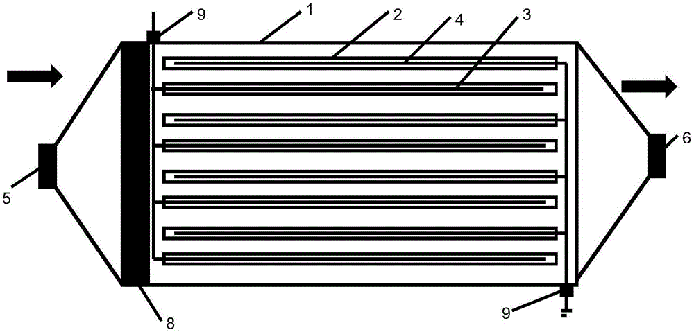
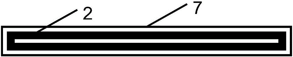
[0027] refer to figure 1 , figure 2 , a dual dielectric barrier discharge device with a catalytic coating for exhaust gas treatment, the dual dielectric barrier discharge device includes a rectangular shell 1, a plate electrode and a number of dielectric plates 2 matching the plate electrode, and the plate electrode is made of stainless steel Made, the medium board is made of plexiglass. The plate electrode includes a high-voltage electrode 3 and a ground electrode 4, and the high-voltage electrode 3 and the ground electrode 4 are covered with corresponding dielectric plates; At the connection point connecting the power supply and the ground wire; the connection points of the high-voltage electrode, the ground electrode and the outside of the casing are respectively provided with insulating ceramics 9 . After the power is turned on, the pollutant gas and background gas in the gas path can be broken down under high pressure, forming a large number of tiny fast pulse discharg...

Embodiment 2

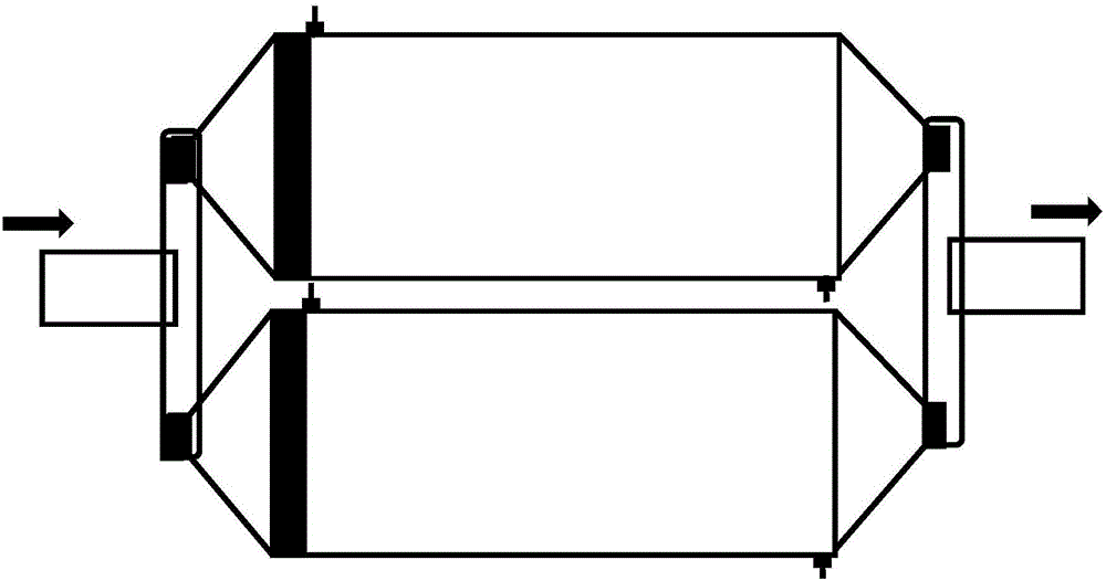
[0033] refer to image 3, for the design of a dual-dielectric barrier discharge device with a catalytic coating for waste gas treatment, not only should attention be paid to the stable occurrence of plasma discharge and the efficient removal of gas pollutants, but also attention should be paid to the treatment of different gas volumes, the dual-dielectric The barrier discharge device is composed of more than two sets of devices connected in parallel. The discharge device of the present invention can be modularized and assembled, and parameters can be adjusted appropriately according to the site conditions of use. Under the condition of large air volume, multiple sets of equipment can be used in parallel to improve the waste gas treatment capacity.

[0034] The invention has the structural characteristics of plasma-catalysis module integration, is used for exhaust gas treatment, and can realize plasma-catalysis efficient and coordinated removal of various gas pollutants such as ...


PUM


Abstract

The invention relates to a double dielectric barrier discharge device with a catalytic coating for waste gas treatment. The double dielectric barrier discharge device comprises a shell; a gas inlet and a gas outlet are formed in the two ends of the shell; a plurality of clamping grooves are formed in the side surface of the shell and are used for allowing plate electrodes and catalytic medium plates to be put in. The double dielectric barrier discharge device provided by the invention has the structure characteristic of plasma-catalytic module integration, is used for waste gas treatment and can not only realize plasma-catalytic efficient synergistic removal of volatile organic compounds, nitrogen oxides and other gaseous pollutants, but also realize the deep oxidation of the pollutants through catalyst formula adjustment aiming at different waste gas components; relative to a two-stage type plasma catalytic device, catalyst modules are reduced, the space is saved, and the pollutant removal efficiency is improved; relative to a traditional one-stage type plasma catalytic device, the caused airflow pressure drop is less, and the energy utilization efficiency is higher; when volatile organic waste gas is treated, the appearance of sediments on the inner wall of a discharge reactor can be effectively inhibited.

Description

technical field [0001] The invention belongs to the technical field of manufacturing gas pollutant control equipment, and in particular relates to a double-dielectric barrier discharge device with a catalytic coating for waste gas treatment. Background technique [0002] Low-temperature plasma technology is an effective exhaust gas treatment technology, which can generate a large number of substances with strong chemical reactivity such as high-energy electrons and OH , O , N free radicals at room temperature, and is effective for nitrogen oxides and volatile organic compounds. It has better processing effect. Glow discharge, corona discharge, radio frequency discharge, sliding arc discharge and dielectric barrier discharge can all generate low-temperature plasma, among which dielectric barrier discharge is widely used in the field of gas pollutant control. [0003] Dielectric Barrier Discharge (DBD) is a non-equilibrium gas discharge that inserts an insulating medium into ...

Claims


Application Information

Patent Timeline
Patent Type & Authority Applications(China)
IPC IPC(8): B01D53/86B01D53/54B01D53/44
CPCB01D53/323B01D53/8628B01D53/8687B01D2259/818Y02A50/20
Inventor 高翔竺新波郑成航岑可法倪明江骆仲泱周劲松杨洋翁卫国吴卫红张涌新蔡宇翔赵冲陈梦晗
Owner ZHEJIANG UNIV
Why Eureka
Try Eureka