Device system for continuously trapping CO2 in flue gas of cement kiln through hydrate method

A cement kiln and CO2 technology, applied in the direction of carbon compounds, sustainable manufacturing/processing, educts, etc., can solve the problems of inability to achieve continuous absorption, insufficient separation capacity, and low energy saving

Active Publication Date: 2017-06-13
长沙紫宸科技开发有限公司
View PDF7 Cites 10 Cited by
  • Summary
  • Abstract
  • Description
  • Claims
  • Application Information

AI Technical Summary

Problems solved by technology

This hydrate method has no serious secondary pollution caused by the traditional chemical adsorption method or physical chemical adsorption method, but there are still the following problems: it needs to react for several hours in a closed high-pressure reactor under high-pressure stirring, and the reaction time for hydrate formation It is still too long; the hydration reaction needs to be carried out under electromagnetic stirring in a closed high-pressure container, and the

Method used


Image

  • Device system for continuously trapping CO2 in flue gas of cement kiln through hydrate method
  • Device system for continuously trapping CO2 in flue gas of cement kiln through hydrate method
  • Device system for continuously trapping CO2 in flue gas of cement kiln through hydrate method

Examples


Embodiment 1

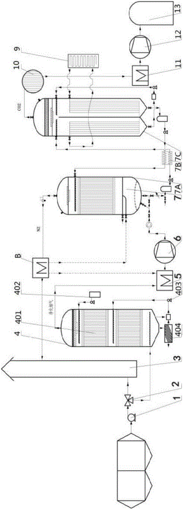
[0054] Such as figure 1 , 4 , 6, the present invention provides a hydrate method to continuously capture CO in cement kiln flue gas 2 The equipment system mainly includes tail exhaust fan 1, electric three-ventilation valve 2, chimney 3, flue gas purification device 4, cooler 5, flue gas compressor 6, CO 2 Absorption tower-regeneration tower unit 7, cold energy recovery device 8, waste heat storage device 9, dehydration dryer 10, CO 2 Cooler 11, CO 2 Compressor 12, liquefied CO 2 The storage tank 13, the electric three-ventilation valve 2 is arranged on the flue gas pipeline between the tail exhaust fan 1 and the chimney 3 connected to the kiln tail dust collector, the gas outlet of the tail exhaust fan 1 and the inlet of the electric air valve 2 The gas ports are connected, the first exhaust port of the electric three-ventilation valve 2 is connected with the flue gas inlet of the flue gas purification device 4, the second exhaust port of the electric three-ventilation va...

Embodiment 2

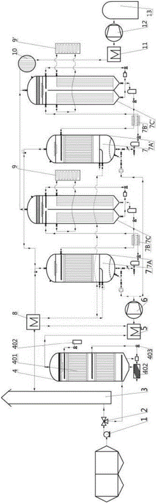
[0064] figure 2 Continuous capture of CO in cement kiln flue gas for the hydrate method described in Example 2 2 Schematic diagram of the equipment system.

[0065] Such as figure 2 , 4 , 6, the difference between this embodiment 2 and embodiment 1 is that it also includes another CO 2 Absorber-regenerator unit 7'; the other CO 2 Absorber-regenerator unit 7' with CO in Example 1 2 Absorber-regenerator unit 7 has the same structure, including CO 2 Absorption tower 7A', lean / rich liquid heat exchange device 7B', CO 2 regeneration tower 7C'; the other CO 2 The absorption tower-regeneration tower unit 7' also has a waste heat storage device 9' to provide the required energy, and the other CO 2 Absorption tower - regeneration tower unit 7' with CO 2 The absorption tower-regeneration tower unit 7 is arranged in parallel; it can double the enrichment of CO 2 Flue gas treatment capacity, effectively increase CO 2 collection efficiency.

Embodiment 3

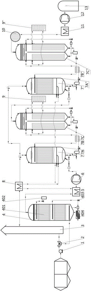
[0067] image 3 Continuous capture of CO in cement kiln flue gas for the hydrate method described in Example 3 2 Schematic diagram of the equipment system.

[0068] Such as image 3 , 4 , 6, the difference between this embodiment 3 and embodiment 1 is that it also includes another CO 2 Absorber-regenerator unit 7"; the other CO 2 Absorber-regenerator unit 7" with CO in Example 1 2 Absorber-regenerator unit 7 has the same structure, including CO 2 Absorption tower 7A", lean / rich liquid heat exchange device 7B", CO 2 regeneration tower 7C"; the other CO 2 The absorption tower-regeneration tower unit 7" also has a waste heat storage device 9" to provide the required energy, and the other CO 2 Absorber-Regenerator Unit 7" with CO 2 The absorption tower-regeneration tower unit 7 is arranged in series, which can effectively increase the CO 2 The purity of the collection.


PUM


Abstract

The invention provides a device system for continuously trapping CO2 in flue gas of a cement kiln through a hydrate method. The device system comprises a tail exhaust fan, an electric three-way air valve, a chimney, a flue gas purifying device, a cooler, a flue gas compressor, a CO2 absorbing tower-regeneration tower unit, a cold energy recovery device, a waste heat energy storage device, a dehydration dryer, a CO2 cooler, a CO2 compressor and a liquefied CO2 storage tank. The CO2 absorbing tower-regeneration tower unit comprises a CO2 absorption tower, a poor/rich fluid heat exchanger device and a CO2 regeneration tower, and the above parts are orderly connected. The device system is based on a cement production line process and process equipment, utilizes cement production waste heat as heat exchange energy, utilizes a hydrate accelerator to continuously capture the CO2 in flue gas of the cement kiln, can purify the flue gas, and realizes high efficiency, low self-consumption, low investment and low operating cost.

Description

technical field [0001] The invention relates to the field of environmental protection and low-carbon technology, in particular to a hydrate method for continuously capturing CO in cement kiln flue gas 2 equipment system. Background technique [0002] Climate change has become one of the issues affecting human survival and development, and carbon dioxide emitted by industry is considered to be the main cause of climate warming. As the largest developing country in the world, our country uses coal as its primary energy and thermal power as its secondary energy as its energy structure. With the rapid growth of economic aggregate, the CO of primary energy and secondary energy 2 Emissions have the characteristics of fast growth and large total volume, but the high investment and high capture cost of the current carbon emission reduction and climate change CCS or CCUS technology have become a serious obstacle to popularization and application. The existing research and demonstr...

Claims


Application Information

Patent Timeline
IPC IPC(8): B01D53/78B01D53/62B01D53/96C01B32/55
CPCB01D53/62B01D53/78B01D53/96B01D2258/0283B01D2257/504Y02P20/129Y02C20/40Y02P20/10Y02P20/50Y02P20/151
Inventor 尹小林
Owner 长沙紫宸科技开发有限公司
Why Eureka
Try Eureka