Air inflation and ignition integrated blaster and fracturing device
A detonator and an integrated technology, applied in the direction of compressed gas generation, blasting barrels, weapon accessories, etc., can solve the problems of high manufacturing cost, eliminate safety hazards, and low blasting power, so as to save mixing materials, avoid safety hazards, and save costs. low effect
- Summary
- Abstract
- Description
- Claims
- Application Information
AI Technical Summary
Problems solved by technology
Method used
Image
Examples
Embodiment 1
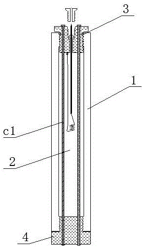
[0081] A gas charge and ignition integrated detonator, such as figure 1 As shown, it includes a tube body 1, a filling cavity 2 and an inflatable ignition head 3. Inside the tube body 1 is a filling cavity 2. One end of the tube body 1 is connected to the gas-filled ignition head 3, and the other end of the tube body 1 is connected to a cover body 4. The compressive strength of the pipe body 1 is greater than 5.045Mpa; the pipe body 1 is a carbon steel cylinder or a stainless steel cylinder, and the filling chamber 2 is filled with a reducing agent and an oxidizing agent, and the oxidizing agent is liquid oxygen, supercritical oxygen or high-pressure gas Oxygen, the reducing agent is carbon-containing organic matter or reducing simple substance.
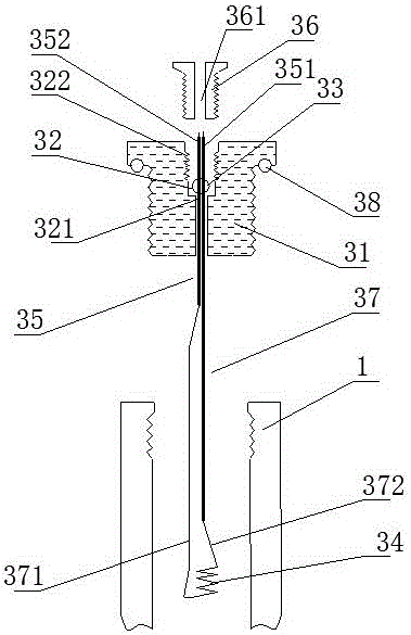
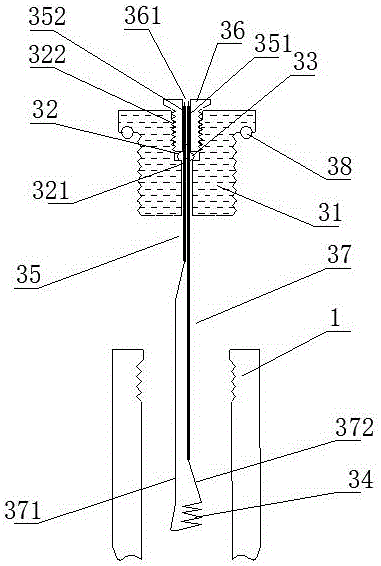
[0082] Such as figure 2 and image 3 As shown, the gas charging ignition head 3 includes a blocking base 31, an air filling hole 32, a sealing ball valve 33, a heating wire 34, a conductive joint 35 and a sealing locking screw 36, a...
Embodiment 2
[0094] The difference with embodiment 1 is: as Figure 4 As shown, the pipe body 1 includes a first segmented body 11 and a second segmented body 12, the first segmented body 11 and the second segmented body 12 are connected through a threaded structure, and are matched with a threaded sealing ring 13 for Sealing; the gas-filled ignition head 3 is respectively connected to one end of the first segment body 11 or the second segment body 11; this structure is convenient for charge.
Embodiment 3
[0096] The difference with embodiment 1 is: as Figure 5 As shown, the pipe body 1 is a composite layer tube containing fiber material, the pipe body 1 is made of a composite layer, and the pipe body 1 includes a matrix layer 101, a fiber layer 102 and a hardened layer 103, and the hardened layer 103 is located at The outer layer of the fiber layer 102, the matrix layer 101 is located in the inner layer of the fiber layer 102; the two ends of the pipe body 1 are respectively sealed and wrapped with a first metal joint 111 and a second metal joint 112, and the first metal joint 111 is threaded The sealing connection structure is connected to the gas ignition head 3, and the second metal joint 112 is connected to the cover body 4; the bottoms of the first metal joint 111 and the second metal joint 112 protrude outwards to avoid falling off from the tube body 1.
[0097] As a further description of the above embodiment, the base layer 101 is made of polyethylene (PE); the fiber l...
PUM
| Property | Measurement | Unit |
|---|---|---|
| Compressive strength | aaaaa | aaaaa |
| Tensile strength | aaaaa | aaaaa |
| Tensile strength | aaaaa | aaaaa |
Abstract
Description
Claims
Application Information
 - R&D
- Intellectual Property
- Life Sciences
- Materials
- Tech Scout
- Unparalleled Data Quality
- Higher Quality Content
- 60% Fewer Hallucinations
Browse by: Latest US Patents, China's latest patents, Technical Efficacy Thesaurus, Application Domain, Technology Topic, Popular Technical Reports.
© 2025 PatSnap. All rights reserved.Legal|Privacy policy|Modern Slavery Act Transparency Statement|Sitemap|About US| Contact US: help@patsnap.com


