N-type crystalline silicon solar battery and preparation method thereof

A solar cell and crystalline silicon technology, applied in circuits, photovoltaic power generation, electrical components, etc., to achieve the effect of simple production process, improved battery efficiency, and guaranteed quality

Inactive Publication Date: 2017-06-13
HEBEI UNIVERSITY
View PDF2 Cites 2 Cited by
  • Summary
  • Abstract
  • Description
  • Claims
  • Application Information

AI Technical Summary

Problems solved by technology

[0003] One of the purposes of the present invention is to provide an n-type crystalline silicon solar cell, in which the back field is realized by the silicon wafer and the low work function material on the back of the silicon wafer, which can solve the problem of the existing diffusion and ion implantation to form the back field Multiple Defects

Method used


Image

  • N-type crystalline silicon solar battery and preparation method thereof
  • N-type crystalline silicon solar battery and preparation method thereof
  • N-type crystalline silicon solar battery and preparation method thereof

Examples


Embodiment 1

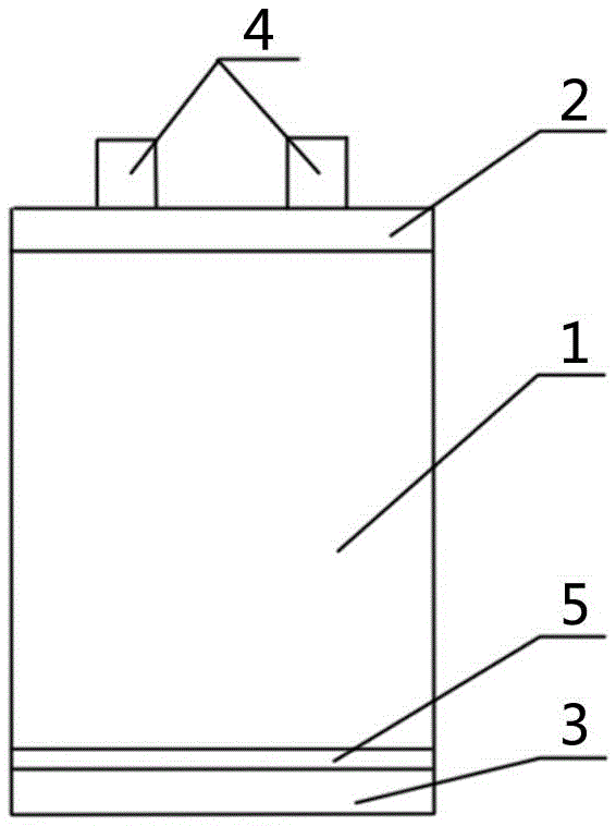
[0031] In this embodiment, the back field of the battery is hybridized with low work function metal magnesium (Mg). The battery structure in this embodiment is as figure 1 As shown: an emitter 2 is formed on the front side of the n-type crystalline silicon 1, a front electrode 4 is formed on the emitter 2, a Mg film layer 5 is formed on the back side of the n-type crystalline silicon 1, and a Mg film layer 5 is formed on the Mg film layer 5. There is a back electrode 3 . The battery in this embodiment is an organic-inorganic hybrid solar battery.

[0032] combine figure 1 , the preparation method of the battery in this embodiment is as follows:

[0033] 1) Treat n-type crystalline silicon 1 .

[0034] In this embodiment, the n-type crystalline silicon 1 is an n-type single crystal silicon wafer. First, the n-type single crystal silicon wafer was polished on both sides, and then the double-sided polished n-type single crystal silicon wafer was cleaned in a hydrofluoric aci...

Embodiment 2

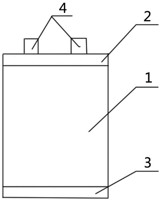
[0057] In this embodiment, the battery back field is hybridized with low work function metal germanium (Ge). The battery structure in this embodiment is as Figure 5 As shown: an emitter 2 is formed on the front side of the n-type crystalline silicon 1, a front electrode 4 is formed on the emitter 2, a Ge film layer 13 is formed on the back side of the n-type crystalline silicon 1, and a Ge film layer 13 is formed on the Ge film layer 13. There is a back electrode 3 .

[0058] combine Figure 5 , the preparation method of the battery in this embodiment is as follows:

[0059] 1) Treat n-type crystalline silicon 1 .

[0060] In this embodiment, the n-type crystalline silicon 1 is an n-type single crystal silicon wafer. First, the front side of the n-type single crystal silicon wafer is polished (that is, the n-type single crystal silicon wafer is polished on one side), and then the front polished n-type single crystal silicon wafer is cleaned in a hydrofluoric acid solution...

Embodiment 3

[0081] In this embodiment, a low work function magnesium-neodymium alloy (MgNd) is used to hybridize the back field of the battery. The battery structure in this embodiment is as Figure 8 As shown: an emitter 2 is formed on the front side of the n-type crystalline silicon 1, a front electrode 4 is formed on the emitter 2, a MgNd film layer 14 is formed on the back side of the n-type crystalline silicon 1, and a MgNd film layer 14 is formed on the MgNd film layer 14 There is a back electrode 3 .

[0082] combine Figure 8 , the preparation method of the battery in this embodiment is as follows:

[0083] 1) Treat n-type crystalline silicon 1 .

[0084] In this embodiment, the n-type crystalline silicon 1 is an n-type single crystal silicon wafer. First, the double-sided texturing of the n-type monocrystalline silicon wafer was performed, and then the double-sided textured n-type monocrystalline silicon wafer was cleaned in a hydrofluoric acid solution with a concentration o...


PUM

PropertyMeasurementUnit
thicknessaaaaaaaaaa
thicknessaaaaaaaaaa
electron work functionaaaaaaaaaa

Abstract

The invention provides an n-type crystalline silicon solar battery and a preparation method thereof. A back field of the n-type crystalline solar battery is realized through n-type crystalline silicon and a low work function material at the back of the n-type crystalline silicon; the low work function material is low work function metal or low work function alloy; the low work function metal can be magnesium, germanium, lithium, neodymium, or calcium, or the like; the low work function alloy can be magnesium-neodymium alloy, magnesium-germanium alloy, magnesium-lithium alloy, germanium-lithium alloy or calcium-magnesium-germanium-lithium alloy. The low work function metal of the low work function alloy is manufactured on the back of the n-type crystalline silicon, so that the band bending can be realized, an n-n+ high-low junction is formed, and then a hole can be driven, an electronic transmission function is enhanced, the battery can acquire high open-circuit voltage and short-circuit current, and the battery efficiency is improved; the preparation process is simple, the cost is low, high temperature and post-annealing treatment are unnecessary, a silicon wafer is not damaged, and the environment cannot be polluted.

Description

technical field [0001] The invention relates to the technical field of crystalline silicon solar cells, in particular to an n-type crystalline silicon solar cell and a preparation method thereof. Background technique [0002] The back field of common n-type crystalline silicon solar cells is mainly realized by secondary diffusion to the surface of the silicon wafer to form heavy doping or ion implantation. The back field formed by diffusion is passed through phosphorus oxychloride (POCl 3 ) decomposes at a high temperature greater than 600°C to form phosphorus pentoxide (P 2 o 5 ) deposited on the silicon wafer surface, P 2 o 5 Reacts with silicon wafers to form silicon dioxide (SiO 2 ) and phosphorus atoms, and form a layer of phosphorus-silicon glass on the surface of the silicon wafer, and then the phosphorus atoms diffuse into the silicon, finally forming a back field. The main problem with this process is that POCl 3 The diffusion source is a toxic liquid, so it ...

Claims


Application Information

Patent Timeline
Patent Type & Authority Applications(China)
IPC IPC(8): H01L31/068H01L31/0224H01L31/18
CPCH01L31/022425H01L31/068H01L31/1804Y02E10/546Y02E10/547Y02P70/50
Inventor 麦耀华陈兵兵葛坤鹏沈艳娇许颖陈剑辉
Owner HEBEI UNIVERSITY
Why Eureka
Try Eureka