Heat repairing method for organic contaminated soil

A technology of organic pollution and remediation method, applied in the field of thermal remediation of polluted soil, can solve the problems of difficulty in exhaust gas compliance, insufficient management, high treatment cost, etc., and achieve the effect of strong thermal decomposition and stabilization

Pending Publication Date: 2017-06-30
CHINESE RES ACAD OF ENVIRONMENTAL SCI
View PDF15 Cites 7 Cited by
  • Summary
  • Abstract
  • Description
  • Claims
  • Application Information

AI Technical Summary

Problems solved by technology

At present, among the polluted sites, there are a large number of organic polluted sites in my country, high cost of treatment, and lack of mature engineering technology, which has become a difficult problem for soil treatment in our country.
Thermal remediation technology is one of the important technologies in the remediation technology of organically polluted sites. The traditional soil remediation technology originated from developed countries. In the practice of site remediation in my country, it is difficult to promote due to high remediation costs, difficulty in exhaust gas compliance, and insufficient management.

Method used


Image

  • Heat repairing method for organic contaminated soil
  • Heat repairing method for organic contaminated soil
  • Heat repairing method for organic contaminated soil

Examples


Embodiment 1

[0032] Before the thermal restoration, the soil in the organic polluted area was first tested, and the test results showed that the average depth of the polluted soil reached more than 2 meters, so the depth of the trench in this embodiment was 3 meters. For areas with less pollution, the depth of the trench can be between 1-2 meters.

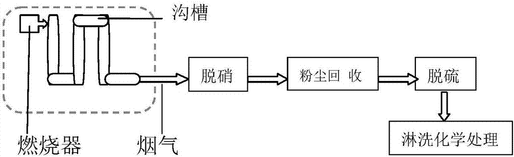
[0033] This example is the in-situ thermal restoration of organically polluted soil, the operation process is shown in figure 1 , including the steps:

[0034] (1) Dig a through trench in the area where the polluted site is located; the trench dug out in the polluted site has a depth of 3m, a width of 1m, and a length of 20m, and the other end of the trench is connected to the combustion furnace through the flue gas circulation pipeline 201 .

[0035] (2) Put the insulation cover on the groove, cover the upper part of the groove completely, and seal the gap of the cover with soil;

[0036] (3) One end of the trench is the flue gas inlet, whi...

Embodiment 2

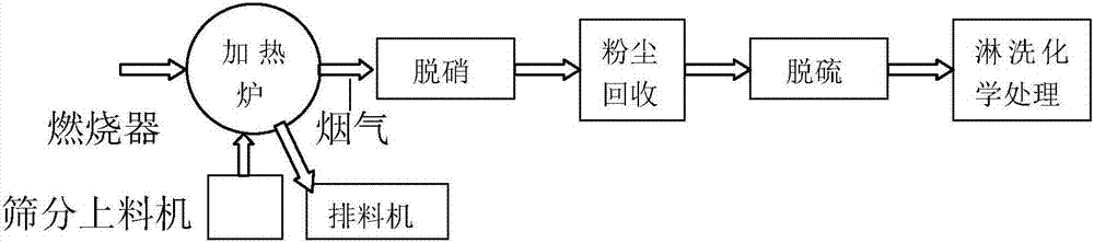
[0043] This example is an ex situ thermal remediation method for organically polluted soil. For the process, see figure 2 .

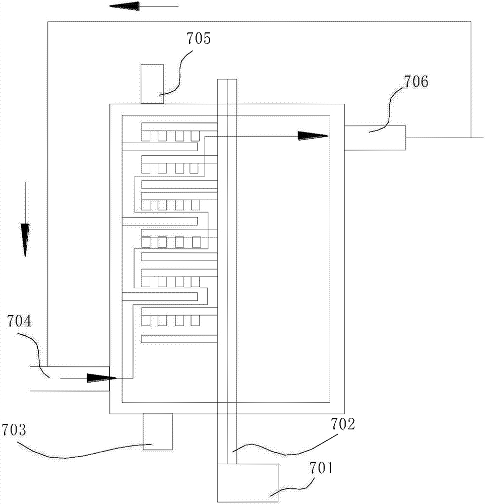
[0044] The operation steps are: excavate the organic polluted soil, send it to the screening feeder, and send the screened polluted soil into the heating furnace by the polluted soil inlet 705 on the top of the heating furnace (see image 3 ), the center of the heating furnace 7 is equipped with a rotating shaft 702, which is driven to rotate by the frequency conversion reducer 701; six layers of rake teeth are arranged on the rotating shaft 702, and the rake teeth correspond to the six layers of sieve plates for placing the soil; the sieve plates are singular in order and fixed There is a feeding channel between the furnace wall and the rotating shaft; the sieve plates are even-numbered in order, fixed on the rotating shaft, and there is a feeding channel between the furnace wall. The rotating shaft drives the rake teeth to unload the contaminated so...


PUM


Abstract

The invention provides a heat repairing method for organic contaminated soil. Smoke of a combustion furnace is used for heating the organic contaminated soil in an in-situ or different-position manner, and heavy metal type pollution, pesticide type pollution, hydrocarbon pollution and biology and nutrient type pollution are separated from the soil. According to the method, the strong heat decomposition and stabilizing functions are achieved for the pollutants which belong to the heavy metal type such as chromium, cadmium, mercury, arsenic, lead, copper, zinc and nickel; the organic pollutants which belong to the pesticide type such as insecticide, acaricide, bactericide, herbicide, nematicide and a plant growth regulator can be effectively desorbed at the high temperature; the extremely high pyrolysis effect is achieved for hydrocarbon pollutants including petroleum hydrocarbon, halohydrocarbon, polycyclic aromatic hydrocarbon and the like; and the biology and nutrient type pollutants can be completely decomposed at the high temperature.

Description

technical field [0001] The invention belongs to the technical field of thermal restoration of polluted soil, and in particular relates to a method for repairing polluted soil by means of heating. Background technique [0002] Contaminated sites are space areas formed by the use or accumulation of hazardous substances by humans in various activities, which are harmful to human health and the environment or have potential risks. Contaminated sites have become a worldwide environmental problem. constitute a serious hazard to humans and the environment. With the rapid development of my country's economy and the adjustment of economic structure, the improper disposal of industrial "three wastes", unreasonable stacking of tailings in mining areas, oil and gas mining, and the relocation of urban industrial areas have become increasingly prominent and harmful. It is imperative to control polluted sites in areas with potential and potentially harmful environments. However, the trea...

Claims


Application Information

Patent Timeline
Patent Type & Authority Applications(China)
IPC IPC(8): B09C1/06
CPCB09C1/065
Inventor 侯红唐振生王文杰赵龙马瑾薛文娟
Owner CHINESE RES ACAD OF ENVIRONMENTAL SCI
Why Eureka
Try Eureka