Geological carbon dioxide sequestration structure and sequestration method

A carbon dioxide and geological storage technology, applied in chemical instruments and methods, inorganic chemistry, earthwork drilling, etc., can solve problems such as easy leakage, high cost, natural environment impact, etc., and achieve easy flow, simple detection, and reduced risk. Effect

Pending Publication Date: 2017-06-30
孙铎
View PDF7 Cites 19 Cited by
  • Summary
  • Abstract
  • Description
  • Claims
  • Application Information

AI Technical Summary

Problems solved by technology

[0004] At present, the method of storing carbon dioxide is mainly geological storage. According to the storage medium, it can be divided into deep-water layer supercritical s

Method used


Image

  • Geological carbon dioxide sequestration structure and sequestration method
  • Geological carbon dioxide sequestration structure and sequestration method
  • Geological carbon dioxide sequestration structure and sequestration method

Examples


Embodiment 1

[0051] The purified flue gas with a carbon dioxide content of 90 at.% collected from the power plant is injected into the abandoned oil field to realize carbon dioxide sequestration. The specific process is as follows:

[0052] (1) the waste gas discharged from the power plant is collected to obtain the original flue gas with a carbon dioxide content of 10 at.%;

[0053] (2) After rough treatment, carbon dioxide waste gas with a carbon dioxide content of 90 at.% is obtained, and the other 10 at.% is nitrogen;

[0054] (3) The obtained mixed gas is mixed with 10 under the standard state 4 m 3 Inject at a rate of 500 meters per day into fully exploited oilfields with a porosity of 0.3 and a water saturation of 0.3;

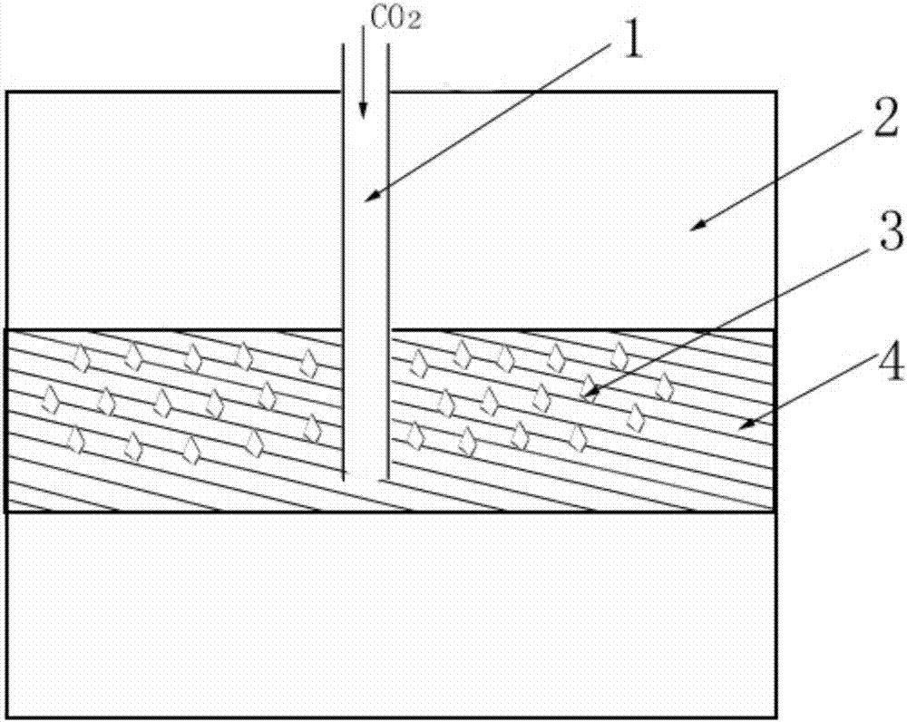
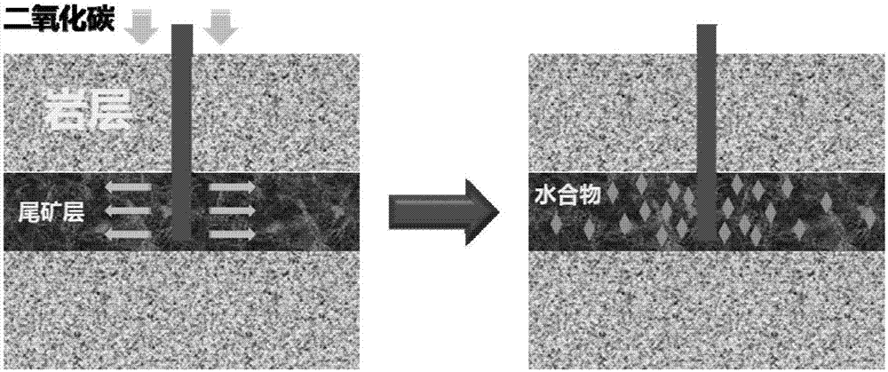
[0055] (4) if figure 2 As shown, the injected mixed gas containing carbon dioxide diffuses downhole to the far end, and finally forms solid hydrate with water under appropriate temperature and pressure conditions, realizing the geological storage of carbon dioxi...

Embodiment 2

[0057] The flue gas is collected from the refinery and injected into the exploited gas field after rough treatment to realize carbon dioxide sequestration. The specific process is as follows:

[0058] (1) collecting the waste gas discharged from the refinery to obtain the original flue gas with a carbon dioxide content of 15 at.%;

[0059] (2) After rough treatment, the carbon dioxide waste gas obtained with a carbon dioxide content of 88 at.%, wherein the other 10 at.% is nitrogen, and 2 at.% is oxygen;

[0060] (3) The obtained mixed gas is mixed with 10 under the standard state 3 m 3 Inject at a rate of / day into fully exploited gas fields with a porosity of 0.2 and a water saturation of 0.4 at a depth of 300 meters;

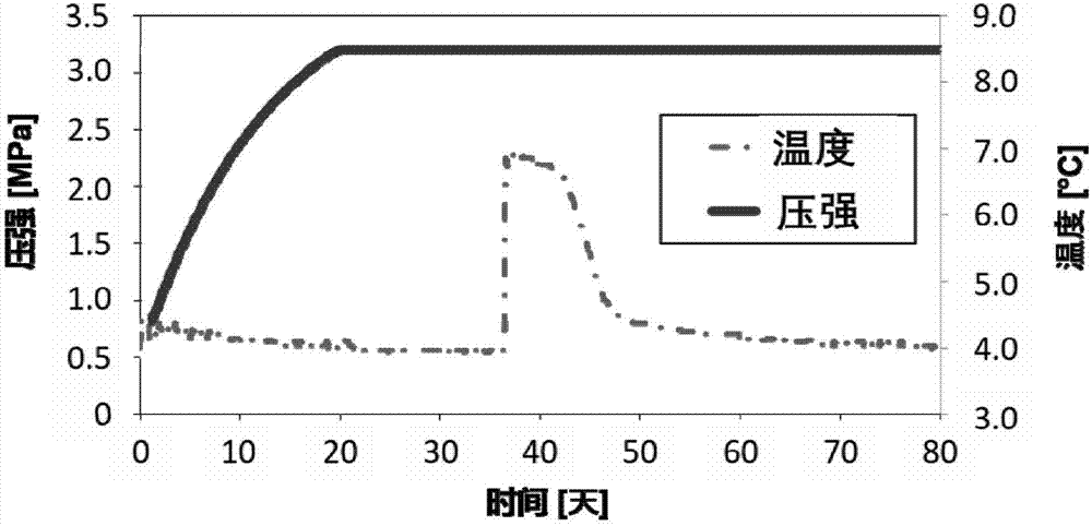
[0061] (4) if figure 2 As shown, the injected carbon dioxide gas mixture forms solid hydrates with water in the downhole under appropriate temperature and pressure conditions, realizing the geological storage of carbon dioxide. Such as image 3 As shown...

Embodiment 3

[0063] The downhole temperature and pressure of abandoned oil fields and gas fields injected with mixed gas containing carbon dioxide were monitored, and the conditions were found to be in the thermodynamic range where carbon dioxide hydrate is stable. There is no possibility of phase transition of hydrate, and it is determined that there is no risk of leakage of stored carbon dioxide gas.


PUM


Abstract

The invention discloses a geological carbon dioxide sequestration structure and sequestration method and belongs to the technical field of carbon dioxide sequestration and environmental protection. The carbon dioxide produced in industrial production is recovered in a centralized mode and injected into abandoned oil fields and gas fields to make carbon dioxide and underground water generate a solid carbon dioxide hydrate, and the sequestration and emission reduction purposes are achieved. The carbon dioxide hydrate related in the invention has the characteristic of containing ultra-volume gas and can be safety saved under the stable geological conditions verified over thousands of years, and the leakage risk is greatly reduced. In addition, a well area device for oil and gas extraction injects carbon dioxide to the position 300-500 meters away from the ground, and the sequestration cost is greatly reduced. In consideration of policy making and implementation for carbon dioxide emission reduction in our country or even throughout the word, the geological carbon dioxide sequestration structure and sequestration method has a very wide market space.

Description

technical field [0001] The invention relates to the technical field of carbon dioxide sequestration and environmental protection, in particular to a carbon dioxide geological sequestration structure and a sequestration method. Background technique [0002] Carbon dioxide hydrate is a relatively special envelope compound formed by water and most gases under low temperature and high pressure conditions. In carbon dioxide hydrate, water molecules form the main crystal network with the help of strong hydrogen bonds, and the pores in the network are filled with gas molecules (called guest molecules), and the degree of filling of the pores depends on the temperature, pressure and excess of the system. coldness. There is no stoichiometric relationship between the host and guest molecules, and the force between the molecules is van der Waals force. At present, the research hotspots on carbon dioxide hydrate are concentrated in the fields of natural gas hydrate exploitation, gas st...

Claims


Application Information

Patent Timeline
IPC IPC(8): C01B32/55E21B41/00E21F17/16
CPCE21B41/0064E21F17/16Y02C20/40
Inventor 孙铎
Owner 孙铎
Why Eureka
Try Eureka