
Continuously operated biomass forming fuel gasification combustor

A molding fuel and burner technology, applied in the direction of solid fuel combustion, combustion methods, combustion equipment, etc., can solve the problems of low nitrogen oxide concentration, high heat utilization rate, good environmental protection effect, etc., and achieve low nitrogen oxide concentration , High heat utilization rate, good environmental protection effect

Pending Publication Date: 2017-08-11
HAILUN LIMIN ENERGY SAVING BOILER MFG
View PDF14 Cites 2 Cited by
  • Summary
  • Abstract
  • Description
  • Claims
  • Application Information

AI Technical Summary

Problems solved by technology

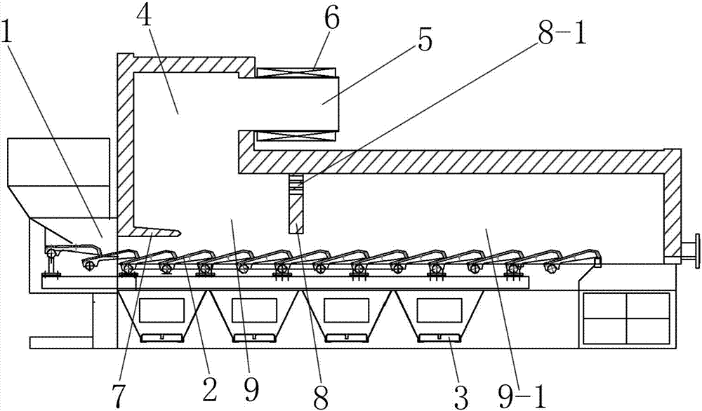
[0005] The beneficial effects of the present invention are as follows: the problem of intermittent operation of the existing burner due to slagging is solved; since the reciprocating grate is used, it can continuously feed materials, continuously discharge slagging, and prevent slagging; the temperature in the gasification chamber It can be controlled in a lower temperature range, and it is not easy to slagging while generating gas; the secondary air adopts a swirl structure to prevent the direct current flame from damaging the rear wall, the flame is full and high, and the heat utilization rate is high; the gasification combustion chamber is separated by a partition wall Divided into gasification area and fixed carbon burnout area to achieve staged combustion, the concentration of nitrogen oxides produced is low, and the environmental protection effect is good

Method used


Image

  • Continuously operated biomass forming fuel gasification combustor

Examples


Embodiment Construction

[0009] refer to figure 1 , a continuously operating biomass briquette fuel gasification burner, which includes a burner body, the burner body includes a gasification combustion chamber, a feed port 1 is arranged on one side of the gasification combustion chamber, and the gasification combustion chamber A grate 2 and a primary tuyere 3 are provided at the bottom of the gasification combustion chamber, a gas collection area 4 is provided above the gasification combustion chamber, and a gas nozzle 5 is provided on the side of the gas collection area 4 that is far from the feed port 1. The nozzle 5 is provided with a secondary tuyere 6; the grate 2 adopts a reciprocating grate 2, and the reciprocating motion of the grate 2 can effectively prevent slagging of the biomass molding fuel; An anti-flashback wall 7 is arranged at the edge to prevent the flame from escaping from the feed port 1; a partition wall 8 perpendicular to the direction of the grate 2 is arranged in the gasificati...


PUM


Abstract

The invention discloses a continuously operated biomass forming fuel gasification combustor, belongs to the technical field of combustion of biomass forming fuels, and solves the problems in a traditional biomass forming fuel combustor. The continuously operated biomass forming fuel gasification combustor comprises a combustor body; the combustor body comprises a gasification combustion chamber; a feed port is formed in one side of the gasification combustion chamber; a fire grate and a primary wind port are arranged at the bottom of the gasification combustion chamber; a gas gathering area is arranged above the gasification combustion chamber; a gas nozzle is arranged on one side, farther from the feed port, of the gas gathering area; a secondary wind port is formed in the gas nozzle; the fire grate adopts a reciprocating fire grate; a tempering prevention wall is arranged in the upper side edge position of the feed port in the gasification combustion chamber; an isolation wall perpendicular to the fire grate is arranged in the gasification combustion chamber for dividing the gasification combustion chamber into two areas; an air hole is formed in the upper side of the isolation wall; and cyclone blades are arranged in the secondary wind port. The continuously operated biomass forming fuel gasification combustor is applied to gasification combustion of the biomass forming fuels.

Description

technical field [0001] The invention belongs to the technical field of biomass briquette fuel combustion, and in particular relates to a continuously operating biomass briquette fuel gasification burner. Background technique [0002] Biomass briquettes such as straw particles have many advantages such as high calorific value, environmental protection, and regeneration. The existing biomass briquette fuel burners are prone to slagging in the gasification chamber, and need to be shut down frequently for manual slagging, which cannot Continuous operation; Insufficient combustion; Direct-flow flame is generated, the diameter of the flame is small, the length is large, and it is directly sprayed onto the back wall to cause serious slagging of the back wall, resulting in a short maintenance cycle, and the molten slag on the back wall needs to be cleaned regularly, which is labor intensive and Problems such as low heat utilization rate need to be solved. Contents of the invention...

Claims


Application Information

Patent Timeline
IPC IPC(8): F23B10/00F23L9/00
CPCF23B10/00F23L9/00
Inventor 别如山万显君李锦时王文刘伟冯力万邦国
Owner HAILUN LIMIN ENERGY SAVING BOILER MFG
Learn More