Joint of copper terminal and aluminium conductor and resistance welding method thereof

A resistance welding and copper terminal technology, applied in the field of wire harnesses, can solve the problems of the mechanical and electrical properties of copper terminals and aluminum wire joints, the electrochemical reaction of aluminum wires and copper terminals, and the potential corrosion of copper and aluminum. Achieve the effect of improving the performance of electrochemical corrosion resistance and metal corrosion resistance, reducing preparation time and reducing preparation cost

Inactive Publication Date: 2017-08-29
JILIN ZHONG YING HIGH TECH CO LTD
View PDF7 Cites 6 Cited by
  • Summary
  • Abstract
  • Description
  • Claims
  • Application Information

AI Technical Summary

Problems solved by technology

However, for the combination of copper terminals and aluminum wires, the traditional crimping method cannot solve the electrochemical reaction between the aluminum wires and copper terminals over time, and cannot solve the resulting mechanical properties of the copper terminals and aluminum wire joints and electrical performance degradation
Therefore, it cannot be applied in industrial production
[0005] The existing resistance welding technology is basically based on the welding of the same metal, mostly the welding of steel sheet metal parts, while the resistance welding technology of dissimilar metals is mostly used in the resistance welding of copper and aluminum pipes in air conditioners. For example, the utility model patent CN203147094U describes the copper-aluminum tube resistance welding joint, which is to insert the copper tube shrink into the aluminum tube, and then weld the copper and aluminum together by means of resistance welding. This method is only applicable to the welding of tu

Method used


Image

  • Joint of copper terminal and aluminium conductor and resistance welding method thereof
  • Joint of copper terminal and aluminium conductor and resistance welding method thereof
  • Joint of copper terminal and aluminium conductor and resistance welding method thereof

Examples


Embodiment 1

[0062] Embodiment 1 A joint of copper terminal and aluminum wire and its resistance welding method

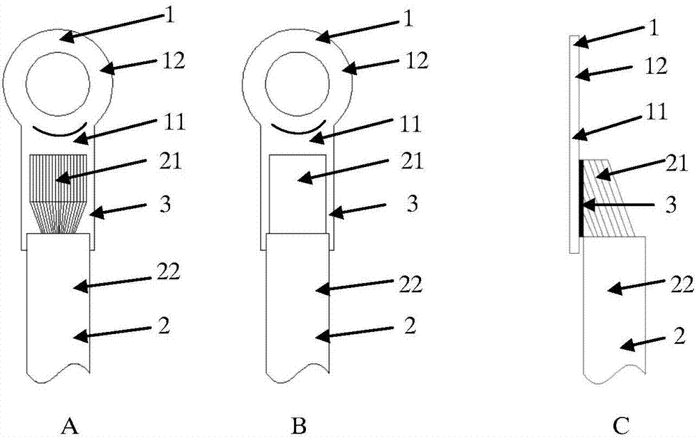
[0063] Such as figure 1 As shown in the joint between the copper terminal and the aluminum wire, the copper terminal 1 is a flat copper terminal, the copper terminal 1 includes a connecting part 11, and a functional part 12, the aluminum wire 2 includes a conductor core 21 and an insulating layer 22, and the aluminum wire It is a multi-core aluminum wire ( figure 1 A) or solid aluminum wire ( figure 1 B). The guide core 21 of the aluminum wire 2 is connected to the connecting piece 11 of the copper terminal 1 , and an interval metal layer 3 is also included between the guide core of the aluminum wire and the connecting piece of the copper terminal.

[0064] The specific welding steps of the joint are as follows:

[0065] 1) The copper terminal is plated with a spacer metal layer (nickel in this embodiment) in the welding area, and the thickness of the spacer metal layer is ...

Embodiment 2

[0068] Embodiment 2 A joint of copper terminal and aluminum wire and its resistance welding method

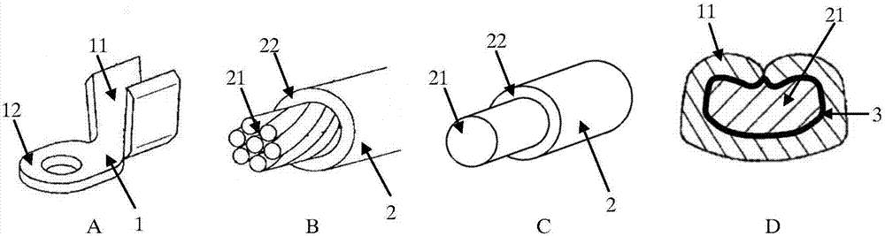
[0069] Such as figure 2 As shown in the joint between the copper terminal and the aluminum wire, the copper terminal 1 is an open terminal, the copper terminal 1 includes a connecting piece 11, and a functional piece 12, the aluminum wire 2 includes a conductor core 21 and an insulating layer 22, and the aluminum wire is Multi-core aluminum wire ( figure 2 B) or solid aluminum wire ( figure 2 C). The guide core 21 of the aluminum wire 2 is connected to the connecting piece 11 of the copper terminal 1 , and an interval metal layer 3 is also included between the guide core of the aluminum wire and the connecting piece of the copper terminal.

[0070] The specific welding steps of the joint are as follows:

[0071] 1) The copper terminal is electroplated with a spacer metal layer (zinc in this embodiment) in the welding area, and the thickness of the spacer metal layer is 5...

Embodiment 3

[0075] Embodiment 3 A joint of copper terminal and aluminum wire and its resistance welding method

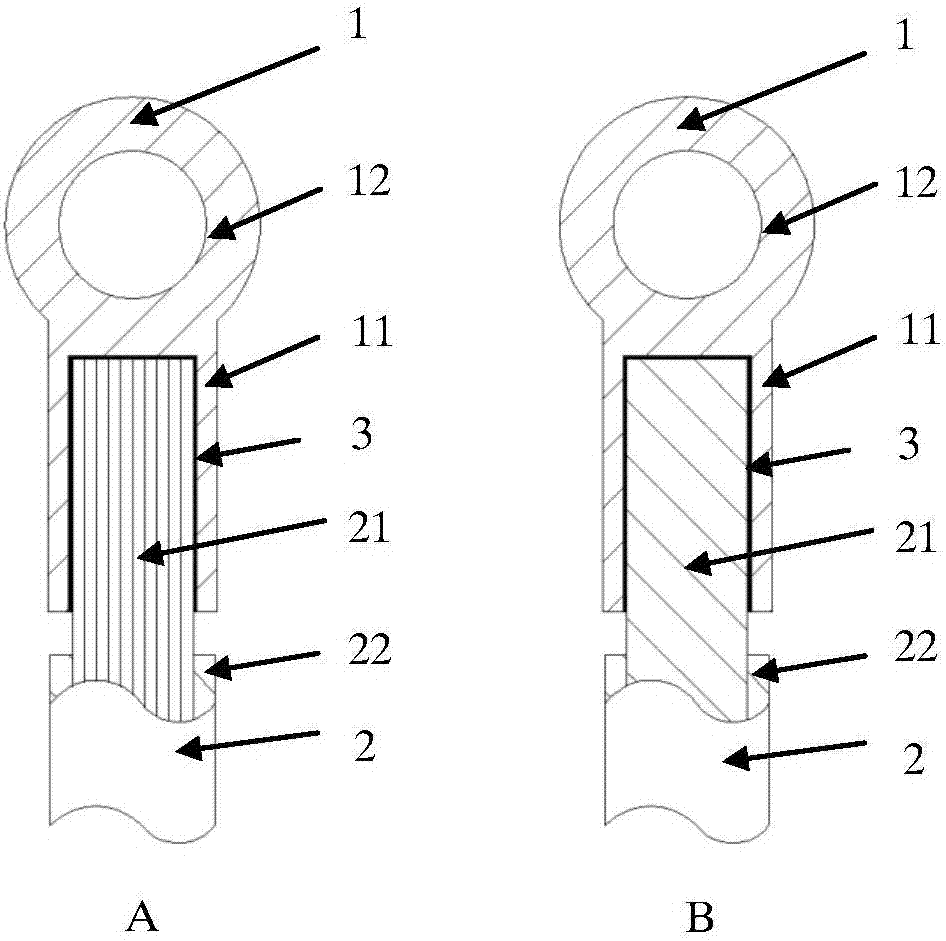
[0076] Such as image 3 As shown in the joint between the copper terminal and the aluminum wire, the copper terminal 1 is a cylindrical terminal, the copper terminal 1 includes a connecting part 11, and a functional part 12, the aluminum wire 2 includes a conductor core 21 and an insulating layer 22, and the aluminum wire It is a multi-core aluminum wire ( image 3 A) or solid aluminum wire ( image 3 B). The guide core 21 of the aluminum wire 2 is connected to the connecting piece 11 of the copper terminal 1 , and an interval metal layer 3 is also included between the guide core of the aluminum wire and the connecting piece of the copper terminal.

[0077] The specific welding steps of the joint are as follows:

[0078] 1) The copper terminal is plated with a spacer metal layer (silver in this embodiment) in the welding area, and the thickness of the spacer metal layer is ...


PUM

PropertyMeasurementUnit
Thicknessaaaaaaaaaa
Thicknessaaaaaaaaaa
Thicknessaaaaaaaaaa

Abstract

The invention belongs to the field of a wire harness, and particularly relates to a resistance welding structure and method between a copper terminal and an aluminium conductor. In order to solve the problems of electrochemical corrosion of welding between the copper terminal and the aluminium conductor and poor mechanical property of a welding joint in the prior art, according to the resistance welding structure and method disclosed by the invention, a separation metal layer is added between the copper terminal and the aluminium conductor; firstly, the separation metal layer is fixed at a welding end of one base metal in a mode of electroplating, pressure welding, arc spray welding or electromagnetic welding and the like; and then the separation metal layer, the copper terminal and the aluminium conductor are welded together. The resistance welding method disclosed by the invention not only is suitable for welding the copper terminal and the aluminium conductor, but also is suitable for welding of various types of joints, electrochemical corrosion caused by a potential difference of copper and aluminium electrodes can be effectively reduced, and the mechanical property of the joint is improved.

Description

technical field [0001] The invention belongs to the field of wiring harnesses, and in particular relates to a joint for connecting copper terminals and aluminum wires in the wiring harness and a resistance welding method thereof. Background technique [0002] In the field of wire harnesses, 90% of wire harnesses currently use copper wires, because copper wires have good electrical conductivity, thermal conductivity, corrosion resistance and mechanical strength. However, as the price of copper increased, people began to look for copper substitutes to reduce costs. The price of aluminum is relatively low, and it also has excellent electrical conductivity, thermal conductivity and plastic workability, and, in the case of conducting the same current, the weight of aluminum wire is about one-third of that of copper wire. Therefore, in traditional cars Under the premise of weight reduction and emission reduction, and new energy vehicles require to reduce vehicle weight, replacing...

Claims


Application Information

Patent Timeline
IPC IPC(8): H01R4/62H01R11/12H01R43/02
CPCH01R4/625H01R11/12H01R43/0214
Inventor 不公告发明人
Owner JILIN ZHONG YING HIGH TECH CO LTD
Why Eureka
Try Eureka