Device and method for removing CO2 in power plant exhaust gas by means of ash slurry

A technology for ash and flue gas, which is applied to chemical instruments and methods, separation methods, gas treatment, etc. It can solve the problems of large pressure drop in the tower, low decarbonization efficiency, and limited flow rate, and achieves low equipment corrosion and degassing. High carbon efficiency and the effect of reducing decarbonization costs

Inactive Publication Date: 2017-09-22
NANJING NORMAL UNIVERSITY
View PDF2 Cites 2 Cited by
  • Summary
  • Abstract
  • Description
  • Claims
  • Application Information

AI Technical Summary

Problems solved by technology

The mechanical stirred tank reactor has the defects of high energy consumption, difficult sealing and easy to produce environmental pollution; although the general bubble tower has a simple structure and good contact between phases, the pressure drop in the tower is large and the flow rate is limited; the ordinary seasoning tower There are also defects such as high cost and low efficiency
It can be seen that although the above-mentioned device can realize the reduction of CO in coal-fired flue gas by ash slurry 2 capture, but its decarbonization efficiency is low, and many other defects are exposed at the same time, the system needs to be further optimized

Method used


Image

  • Device and method for removing CO2 in power plant exhaust gas by means of ash slurry
  • Device and method for removing CO2 in power plant exhaust gas by means of ash slurry
  • Device and method for removing CO2 in power plant exhaust gas by means of ash slurry

Examples


Embodiment 1

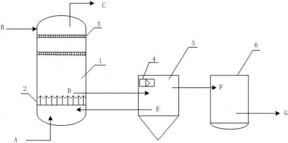
[0033] Such as figure 1Shown, the present invention provides a kind of utilizing ash slurry to remove CO in power plant flue gas 2 The device includes: a reactor 1, a sedimentation tank 5 and a clarifier 6; the upper input end of the reactor 1 is fed into the ash slurry, the lower input end is fed into the desulfurized flue gas from the power plant, and the upper output end is discharged from the decarbonized The output end of the lower end of the flue gas is connected to the sedimentation tank 5; the output end of the sedimentation tank 5 is connected to the clarification tank 6; the output end of the clarification tank 6 is connected to the atmosphere.

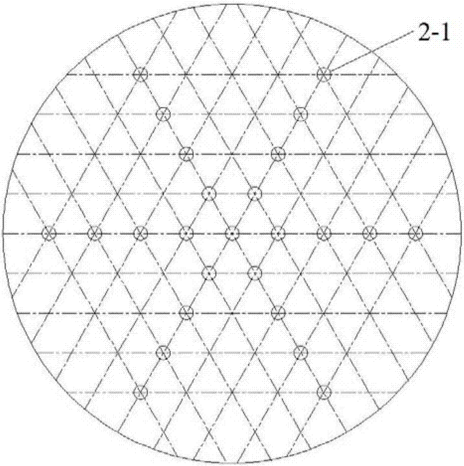
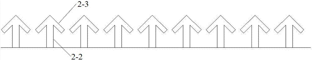
[0034] More specifically, a gas distributor 2 is provided in the reactor 1 . The gas distributor 2 is a circular plate-shaped structure, such as figure 2 As shown, the board is provided with a small hole 2-1 through the board body, and the diameter of the small hole is 30-50mm; image 3 As shown, branch pipes 2-2 are arr...


PUM


Abstract

The invention discloses a device and method for removing CO2 in power plant exhaust gas by means of ash slurry. The device comprises a reaction kettle, a settling pond and a clarification pond, wherein ash slurry is fed into the upper input end of the reaction kettle, exhaust gas obtained after power plant desulfuration is fed into the lower input end, the upper output end is led into the atmosphere, and the lower output end is connected with the settling pond; the output end of the settling pond is connected with the clarification pond. The alkali ash slurry is sufficiently utilized for removing acid CO2 gas in the exhaust gas to generate neutral salt, the pH value of the waste ash slurry can be effectively adjusted, and the discharge limitation standard is reached; on one hand, waste resource utilization can be achieved, and the problem that environment pollution caused by direct discharge of the waste alkali slurry is solved; on the other hand, the system decarburization cost and energy consumption can be effectively lowered. The device is combined with power plant ash slurry, treatment of wastes with processes of wastes against one another can be achieved, and the optimum scheme with the low cost and energy consumption is obtained.

Description

technical field [0001] The invention relates to the field of waste resource utilization and environmental pollution prevention and control in the process of energy utilization, in particular to a method for removing CO in power plant flue gas by using ash slurry 2 The device and method belong to the technical field of carbon emission reduction. Background technique [0002] The issue of global warming caused by the large amount of greenhouse gases emitted during the utilization of fossil fuels and other energy sources is one of the focuses of the international community today. The data show that atmospheric CO 2 Concentrations have grown from 280ppm before the first industrial revolution to 397ppm in 2016. Since 1860, the average global temperature has risen by 0.3-0.6°C. It is urgent to strengthen the control of the amount of greenhouse gases caused by human activities. [0003] Currently, fossil fuels are still the main source of global primary energy consumption. Dat...

Claims


Application Information

Patent Timeline
Patent Type & Authority Applications(China)
IPC IPC(8): B01D53/80B01D53/62
CPCB01D53/62B01D53/80B01D2257/504B01D2258/0283Y02A50/20Y02C20/40
Inventor 梁潇李蔚玲郭亚飞赵传文
Owner NANJING NORMAL UNIVERSITY
Why Eureka
Try Eureka