
Real-time monitoring and detection method for penetration and forming during deep fusion welding for electron beam

A technology of real-time monitoring and detection methods, applied in electron beam welding equipment, measuring electricity, measuring devices, etc., can solve the problems of direct monitoring and control of welding seam quality control, etc., to achieve excellent welding seam quality, improve efficiency, and stable welding process. Effect

Active Publication Date: 2017-09-29
NANJING UNIV OF SCI & TECH
View PDF7 Cites 4 Cited by
  • Summary
  • Abstract
  • Description
  • Claims
  • Application Information

AI Technical Summary

Problems solved by technology

[0004] The present invention aims at the difficulties of direct monitoring of the current electron beam welding process and the control of weld seam quality control, etc., and provides a device capable of real-time measurement and real-time display of the penetrating beam current in the electron beam dynamic welding process. By studying the total electron beam The law of the relationship between the current and the back penetrating beam and the definition of the penetration ratio, thus establishing the weld quality (including welding defects such as welding slippage, welding collapse, and excessive weld size and head ratio) and the electron beam penetration ratio criterion Real-time monitoring of electron beam deep penetration welding and the formation of a monitoring method

Method used


Image

  • Real-time monitoring and detection method for penetration and forming during deep fusion welding for electron beam
  • Real-time monitoring and detection method for penetration and forming during deep fusion welding for electron beam
  • Real-time monitoring and detection method for penetration and forming during deep fusion welding for electron beam

Examples


Embodiment 1

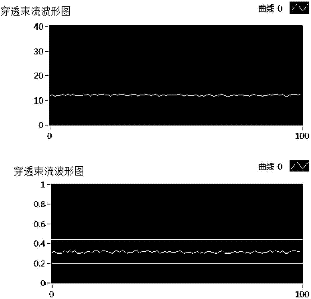
[0058] The 2A12 aluminum alloy used in the experiment has a thickness of 10mm, which has good plasticity at high temperature and good welding performance, but it is easy to oxidize in the air. To remove oil, rust and oxides on the surface of the weldment, especially the two butt surfaces, first use a scraper to scrape off the oxides on the surface, and then use absolute ethanol to scrub and dehydrate.

[0059] Attach welding plate 3 as attached figure 2 Press fit and ensure the accuracy of assembly. The beam current sensing acquisition module 9 is fixed on the base 6 as shown in the accompanying drawings, and placed directly below the weld. It is ensured that the workpiece can slide along with the workbench 1 on the base 6 at a certain welding rate.

[0060] The selected process parameters are acceleration voltage 60kV, electron beam current 20mA, and welding speed 600mm / min. It is ensured that when the electron beam hits the welding plate 3, the worktable 1 starts to move...

Embodiment 2

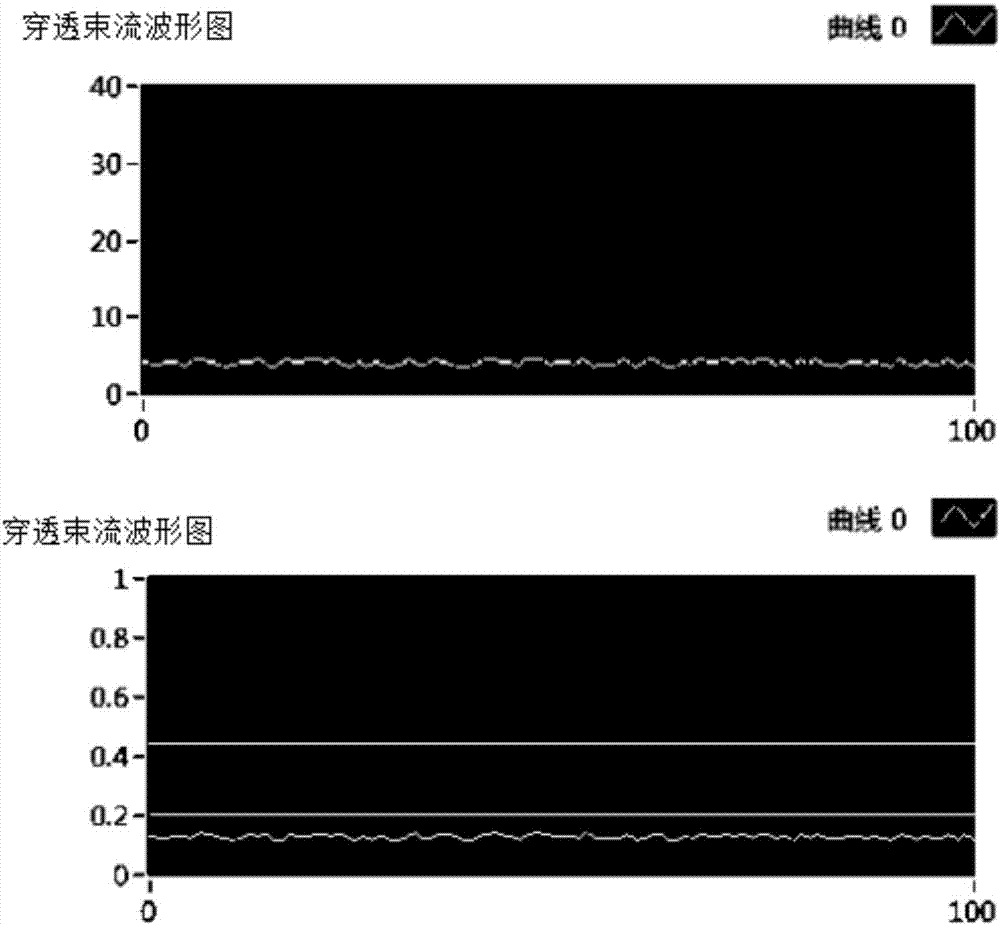
[0068] The TC4 titanium alloy used in the experiment has a thickness of 10mm and is supplied in solution treated state. To remove the oil, rust and oxides on the surface of the weldment, especially the two butt surfaces, first use a scraper to scrape off the oxides on the surface, and then use absolute ethanol to scrub and dehydrate.

[0069] Attach welding plate 3 as attached figure 2 Press fit and ensure the accuracy of assembly. Beam sensing acquisition module fast 9 is fixed on the base 6, and placed directly below the weld. It is ensured that the workpiece can slide along with the workbench 1 on the base 6 at a certain welding rate.

[0070] The selected process parameters are acceleration voltage 60kV, electron beam current 35mA, and welding speed 500mm / min. It is ensured that when the electron beam hits the welding plate 3, the worktable 1 starts to move, and the moving speed of the worktable 1 is the welding speed. At the same time, the beam sensing acquisition mo...

Embodiment 3

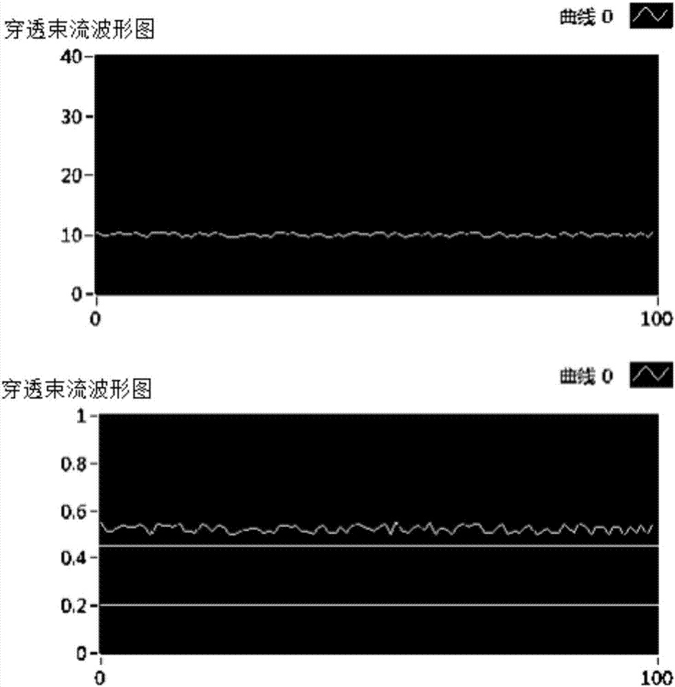
[0078] The high-nitrogen austenitic stainless steel used in the experiment has a thickness of 5mm, which has high strength and high toughness and corrosion resistance. To remove the oil, rust and oxides on the surface of the weldment, especially the two butt surfaces, first use a scraper to scrape off the oxides on the surface, and then use absolute ethanol to scrub and dehydrate.

[0079] Attach welding plate 3 as attached figure 2 Press fit and ensure the accuracy of assembly. Beam sensing acquisition module fast 9 is fixed on the base, and placed directly below the weld. It is ensured that the workpiece can slide along with the workbench 1 on the base 6 at a certain welding rate.

[0080] The selected process parameters are acceleration voltage 60kV, electron beam current 20mA, and welding speed 400mm / min. It is ensured that when the electron beam hits the welding plate 3, the worktable 1 starts to move, and the moving speed of the worktable 1 is the welding speed. At ...


PUM

PropertyMeasurementUnit
Thicknessaaaaaaaaaa
Thicknessaaaaaaaaaa
Thicknessaaaaaaaaaa

Abstract

The invention relates to a real-time monitoring and detection method for penetration and forming during deep fusion welding for an electron beam. Based on the law of total electron beam current and back penetration beam current relationship, the monitoring and detection method forms a criterion through the research to the law to monitor the deep fusion welding for the electron beam in real time. The real-time monitoring and detection method comprises the steps: setting welding parameters such as an electron beam current Iw, etc., and conducting welding; in the welding process, collecting real-time penetration beam currents I1, I2 and Ic through a beam current sensing and collecting module; according to a penetration current ratio Ro=Ic / Iw, calculating the penetration current ratio Ro; displaying the penetration beam current Ic measured in real time and the calculated penetration current ratio Ro on a computer. Through the monitoring method, process parameters can be adjusted, therefore a high-quality weld seam is obtained, and the efficiency is improved in the mass welding process. In the process of dynamic welding, through the criterion of the penetration current ratio, the site with welding defects on a welding plate can be found in real time, but the welding defects are unable to be seen by the naked eye on the welding plate generally.

Description

technical field [0001] The present invention relates to the field of metal material processing, especially a set of beam collection and display device, which is a real-time monitoring device for electron beam welding by collecting and displaying the penetrating beam current during dynamic welding of electron beams in real time. The detection method used is based on the overall The relationship law between the electron beam current and the back penetrating beam current, through the study of the law to form a criterion to monitor the electron beam deep penetration welding in real time and form a monitoring method. Background technique [0002] Electron beam welding is to use the electrons generated by the cathode in the electron gun to be pulled out under the action of a high-voltage (25-300kV) accelerating electric field between the cathode and anode, and accelerated to a very high speed (0.3-0.7 times the speed of light). After the secondary magnetic lens is focused, a dense...

Claims


Application Information

Patent Timeline
IPC IPC(8): B23K15/00G01R31/00
CPCB23K15/0026G01R31/00
Inventor 周琦陈鑫彭勇李洪强王克鸿孔见黄俊郭顺张天齐
Owner NANJING UNIV OF SCI & TECH
Learn More