Microfluidic chip and application thereof

A microfluidic chip and flow channel technology, applied in laboratory containers, measuring devices, instruments, etc., can solve the problems of low reaction efficiency, single flow channel structure, problems with repeatability and accuracy of results, etc. The effect of stabilizing the reaction environment, improving the detection accuracy, and reducing the risk of contamination

Active Publication Date: 2017-11-07
深圳市海拓华擎生物科技有限公司
View PDF6 Cites 11 Cited by
  • Summary
  • Abstract
  • Description
  • Claims
  • Application Information

AI Technical Summary

Problems solved by technology

[0008] However, in the prior art, there are few related materials combining immunoturbidimetry with microfluidic chips. For example, Chinese patent 200910114403.8 describes a method for the determination of substances in a single human red blood cell by chemiluminescence using a microfluidic chip. Rely on a microscope platform or a complex optical path composed of lenses and filters; Chinese patent 200910154432.7 discloses a microfluidic chip for capillary electrophoresis separation and chemiluminescence detection. The flow path structure is single, and the sample injection is not fully mixed, resulting in low reaction efficiency , there are problems with the repeatability and accuracy of the results

Method used


Image

  • Microfluidic chip and application thereof
  • Microfluidic chip and application thereof
  • Microfluidic chip and application thereof

Examples


Embodiment 1

[0069] Embodiment 1 is the microfluidic chip that ferritin (FER) detects

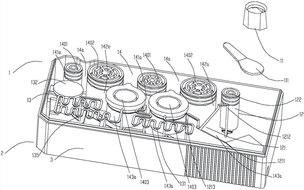
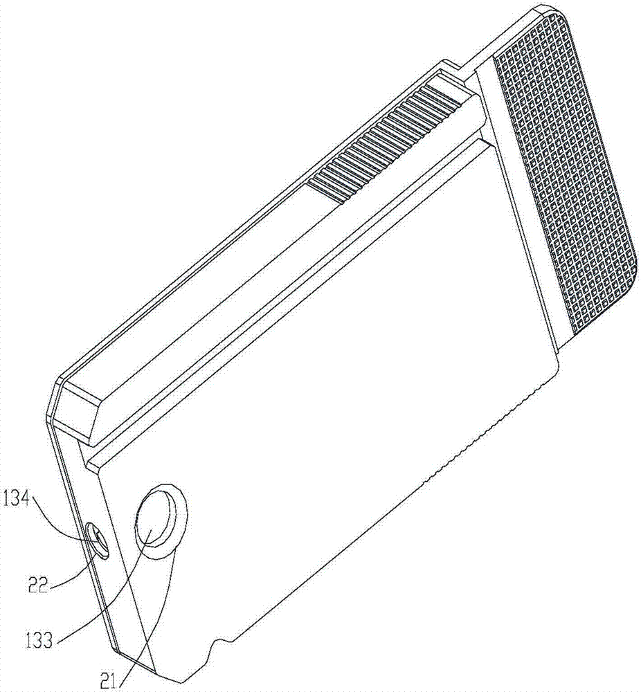
[0070] As in the structure of the microfluidic chip in the specific embodiment,

[0071] Wherein the buffer in the buffer chamber is a phosphate buffer;

[0072] Wherein the composition of the first reagent is:

[0073] TRIS buffer

0.18mol / L, pH=7.5

NaCl

100mmol / L

Antiseptic ProClin 300

0.08%

[0074] pH of the first reagent = 8.2;

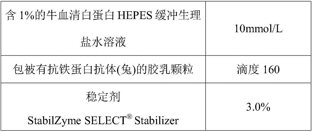
[0075] The composition of the second reagent is:

[0076]

[0077]

[0078] The fabricated microfluidic chip was put into an aluminum foil bag, sealed and stored at 4°C.

[0079] Detection of microfluidic chips:

[0080] Sample pretreatment: Use normal human plasma as the diluent to dilute the ferritin standard to the following concentrations: 5ng / mL, 10ng / mL, 100ng / mL, 500ng / mL, 1000ng / mL, 3000ng / mL and 5000ng / mL;

[0081] Adding samples: put the microfluidic chip into the supporting instrument, add 20 μL sample from the i...

Embodiment 2

[0090] Embodiment 2 is the microfluidic chip that immunoglobulin A (IGA) detects

[0091] As in the structure of the microfluidic chip in the specific embodiment,

[0092] Wherein the buffer in the buffer chamber is a phosphate buffer;

[0093] Wherein the composition of the first reagent is:

[0094] hydroxymethylaminomethane buffer

20mmol / L

NaCl

200mmol / L

polyethylene glycol

3.6%

Gentamicin Sulfate

0.02%

[0095] The pH of the first reagent is 8;

[0096] The composition of the second reagent is:

[0097] Anti-human IGA antibody (goat)

Titer 95

hydroxymethylaminomethane buffer

20mmol / L

NaCl

150mmol / L

Gentamicin Sulfate

0.02%

[0098] The pH of the second reagent is 8.

[0099] The fabricated microfluidic chip was put into an aluminum foil bag, sealed and stored at 4°C.

[0100] Detection of microfluidic chips:

[0101] Sample pretreatment: use phosphate buffer as the dil...


PUM


Abstract

The invention discloses a microfluidic chip. The microfluidic chip comprises a substrate and a bottom cover, wherein a sample inlet, a diluent chamber, a detection chamber and a mixing area are arranged on the substrate; the mixing area comprises a reagent chamber, an air chamber and a uniform mixing chamber; the sample inlet, the diluent chamber and the uniform mixing area are communicated through a first flow passage; the detection chamber is communicated with the uniform mixing chamber through a second flow passage; the reagent chamber is communicated with the uniform mixing chamber through a reagent flow channel; the air chamber is communicated with the uniform mixing chamber through an air channel; a light transmitting panel is arranged on the upper surface of the detection chamber, a light transmitting bottom plate is arranged on the lower surface, and a light transmitting side plate is arranged on the side surface. By means of the microfluidic chip, all reagent components required for a reaction can be integrated onto the chip and do not contact with the outside during the reaction, so that the risk of contamination is greatly reduced; the microfluidic chip is used for detecting the content of to-be-detected components in a sample; reaction time is short, sensitivity is quite high and quantitation is accurate.

Description

technical field [0001] The invention relates to a microfluidic chip and its application, belonging to the technical field of chip detection. Background technique [0002] As more and more specific proteins are used clinically, their detection methods are also developing rapidly. Before 1959, the classical immunoprecipitation method has been used for detection, which has the disadvantages of narrow measurement range, low sensitivity, cumbersome and time-consuming, and cannot be automated. In 1959, Schultze et al. reported Transmission Turbidimetry. This method is commonly used in the determination of biochemical indicators and for the detection of specific proteins, but it has problems such as low sensitivity and narrow measurement range. In recent years, on the basis of immunoturbidimetry, latex-enhanced turbidimetry has emerged. This method uses tiny latex particles with a particle size of about 1 μm to bind antibodies, and then reacts with the corresponding antigen in t...

Claims


Application Information

Patent Timeline
Patent Type & Authority Applications(China)
IPC IPC(8): B01L3/00G01N33/558
CPCB01L3/5027B01L2200/10G01N33/558
Inventor 何毅
Owner 深圳市海拓华擎生物科技有限公司
Why Eureka
Try Eureka