Micro-area semi-solid additive manufacturing method

A kind of additive manufacturing and semi-solid technology, applied in the direction of manufacturing tools, additive processing, welding/cutting media/materials, etc., can solve problems such as inconvenient operation, affecting processing efficiency, and not fundamentally solving problems, so as to eliminate air holes Effect

Active Publication Date: 2020-01-03
BEIJING UNIV OF TECH
View PDF4 Cites 0 Cited by
  • Summary
  • Abstract
  • Description
  • Claims
  • Application Information

AI Technical Summary

Problems solved by technology

Although these methods can alleviate the above-mentioned problems to a certain extent, they require special equipment, additional processes, inconvenient operation, and affect processing efficiency. Some large-sized components cannot even be processed or cost a lot.
In short, these methods have alleviated the degree of these defects to a certain extent, but have not fundamentally solved the problem

Method used


Image

  • Micro-area semi-solid additive manufacturing method
  • Micro-area semi-solid additive manufacturing method
  • Micro-area semi-solid additive manufacturing method

Examples


specific Embodiment approach 1

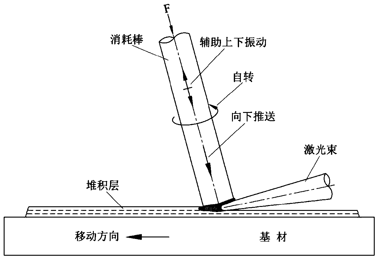
[0028] Specific implementation mode 1: The material of the consumables in this embodiment is 304 stainless steel round rods, the diameter The base material is Q235 low carbon steel, the angle between the consumable rod and the accumulation layer is 75°, the angle between the laser beam and the accumulation layer is 15°, the laser power: 4KW, the laser focus spot is rectangular, and the size is 6mm×1mm.

[0029] The specific forming process includes the following steps:

[0030] 1. Establish a 3D model of metal parts, complete the slicing process through software and generate machine processing paths;

[0031] 2. Remove the oxide film and dirt on the surface of the substrate and consumables;

[0032] 3. Arrange the relative positions of consumables, substrate and laser according to the setting, fix the substrate, and clamp the consumables with three claws with water cooling;

[0033] 4. Turn on the power to make the three claws carry the rod-shaped consumables to rotate at a...

specific Embodiment approach 2

[0040] Specific embodiment 2: The difference between this embodiment and specific embodiment 1 is that the consumables are two pieces arranged side by side with a diameter of The metal bar, other steps and parameters are the same as in Embodiment 1.

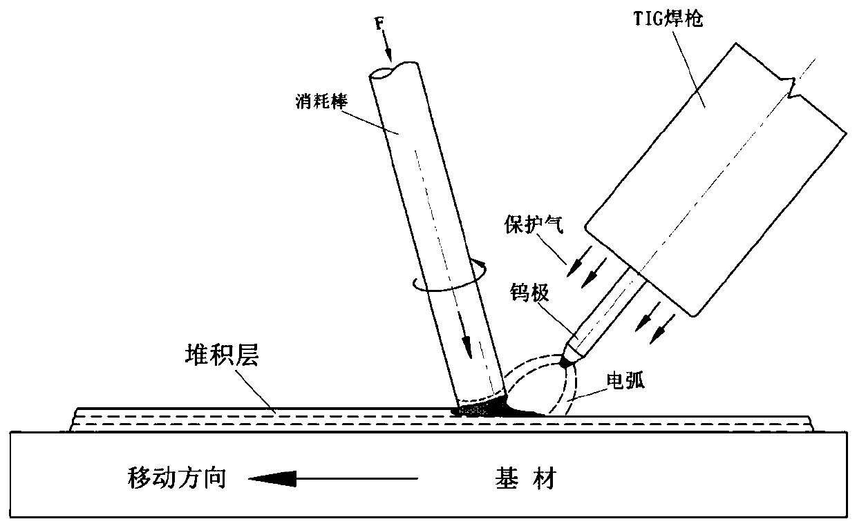
specific Embodiment approach 3

[0041] Specific implementation mode three: as image 3 , the difference between this embodiment and the specific embodiment one is: the heat source is Tig, the angle between the welding torch and the accumulation layer is 55°, and the diameter of the consumption rod is The angle between the consumable rod and the accumulation layer is 60°, the current is 200A, the processing speed is 0.3m / min, the axial thrust of the consumable is 100N, and other steps and parameters are the same as those in Embodiment 1.


PUM

PropertyMeasurementUnit
lengthaaaaaaaaaa
angleaaaaaaaaaa

Abstract

The micro-area semi-solid additive manufacturing method proposed by the present invention mainly solves the problems of structural uniformity, performance reliability, stress and deformation, pores and cracks of formed parts. Using rod-shaped materials as consumables, heating methods such as high-energy beams, electric arcs, and resistance heating are used to act on the front end of the consumables and make them in a semi-solid state where solid and liquid coexist. At the same time, the rotational torque and axial thrust exerted on the consumables have The semi-solid metal undergoes intense shearing, stirring and extrusion, that is, undergoes no-mode semi-solid rheological deformation. In this way, the consumables continuously transition to the underlying metal and form a metallurgical bond with it, and repeat the stacking process according to the planned path after discretization and slicing to form a solid part or stacked layer of a specific shape. The invention has simple operation process, excellent product performance, overcomes many defects of traditional additive manufacturing, and has broad application prospects in the forming of large components, repairing of damaged parts and preparation of composite materials.

Description

technical field [0001] The invention relates to the technical field of metal additive manufacturing, and in particular provides a metal additive manufacturing method with metal semi-solid processing properties. Background technique [0002] In the existing metal additive manufacturing technology, due to multiple non-equilibrium thermophysical processes and metallurgical processes, the component structure, performance uniformity and stability are poor, the tendency of deformation and cracking is serious, and defects such as pores, shrinkage cavities and lack of fusion are prone to occur. The problem seriously affects the service performance of additive parts, and also brings great difficulties to the development and promotion of additive manufacturing technology. [0003] Usually, post-densification treatment is required to solve defects such as pores: usually hot isostatic pressing treatment; heat treatment is used to control the microstructure morphology; preheating, heat t...

Claims


Application Information

Patent Timeline
Patent Type & Authority Patents(China)
IPC IPC(8): B23K28/00B23K3/06
CPCB23K3/0607B23K28/00B23K20/1215B23K9/04B23K10/027B23K11/0013B23K15/0086B23K26/342B33Y10/00B33Y70/00B23K26/082B23K26/1464B23K35/00
Inventor 杨武雄邹江林徐洁洁肖荣诗
Owner BEIJING UNIV OF TECH
Why Eureka
Try Eureka