A method for studying photodissociation at low temperature

A photo-separation and low-temperature technology, which is applied to the parts of particle separator tubes, particle separation tubes, dynamic spectrometers, etc., can solve problems affecting experimental accuracy, broadening, long data acquisition time, etc., to improve energy accuracy and structure Compact and simple, the effect of increasing energy resolution

Active Publication Date: 2019-01-11
TIANJIN ZERUICHI TECH CO LTD
View PDF7 Cites 0 Cited by
  • Summary
  • Abstract
  • Description
  • Claims
  • Application Information

AI Technical Summary

Problems solved by technology

Since the internal energy of the molecular beam will be reintroduced during the ionization process, resulting in an increase in its vibrational freedom, the spectrum obtained by the detector will cause broadening and affect the accuracy of the experiment. Therefore, it is necessary to cool the ion beam as much as possible in the experiment.
[0003] In the existing cooling technology, the purpose of reducing the internal energy of ions is achieved by embedding molecules into atomic clusters such as helium clusters or using radio frequency ion traps in a cooled buffer gas atmosphere to store ions. However, the above cooling technologies are not suitable for Photo-induced separation simultaneous measurement experiment
In addition, photo-separation synchronous measurement experiments generally require high duty cycle and low event rate to avoid data confusion. In this way, some low repetition rate techniques require longer data acquisition time or increase the difficulty of separating pseudo-events. Can not make the photo-separation synchronous measurement experiment be implemented under the situation of ion cooling, or the cooling process does not improve the experimental results, the method of studying photo-separation under the described a kind of low temperature can solve the problem

Method used


Image

  • A method for studying photodissociation at low temperature

Examples


Embodiment Construction

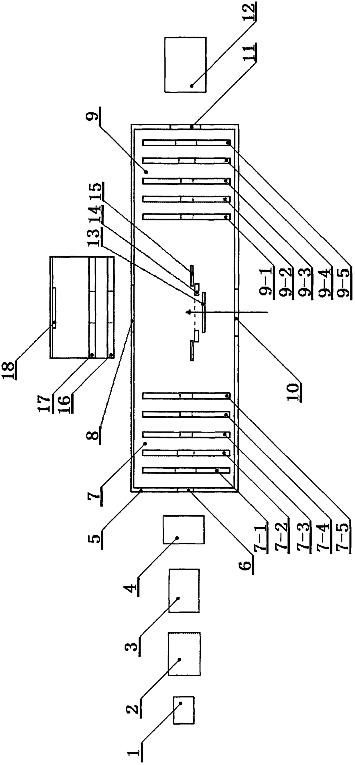
[0020] Such as figure 1It is a schematic diagram of the structure of the present invention. The device for studying photo-induced separation at low temperature is located in an ultra-high vacuum environment, and mainly includes an ion source (1), an accelerator (2), a time-of-flight mass spectrometer (3), a particle mass selector (4), a magnetic Shielding cover (5), ion beam entrance (6), electrode I (7-1), electrode II (7-2), electrode III (7-3), electrode IV (7-4), electrode V (7 -5) Focusing electrode group (7), photoelectron outlet (8), composed of electrode VI (9-1), electrode VII (9-2), electrode VIII (9-3), electrode IX (9-4) , mass selection electrode group (9) composed of electrode X (9-5), laser entrance (10), ion exit (11), ion detector (12), electronic background reduction plate (13), reflection plate (14) , ion correction plate (15), extraction electrode (16), beam focusing electrode (17) and electron detector (18), described focusing electrode group (7), mass se...


PUM


Abstract

The invention relates to the field of photoelectron and molecular reaction dynamics, and provides a method for researching photodetachment under low temperature. Ions are accelerated to pass the time of flight mass spectrum and a particle mass selector and then form an ion beam fragment to enter a magnetic shielding cover from the ion beam entrance; the voltage of a focusing electrode group is set as zero, the voltage is applied to a mass selection electrode group, and the voltage of all the electrodes increases by the same slope; after the ion beam fragment passes the focusing electrode group, a pulse electric field is applied to the focusing electrode group so that the voltage of all the electrode is enabled to increase in order; after the ions leave the mass selection electrode group, the voltage of the mass selection electrode group is set as zero, and the precursor ions reflected by the mass selection electrode group are irradiated by laser in the interaction area near an ion correction board to generate ion fragments and photoelectrons; the ion fragments fly to the focusing electrode group to be reflected and fly to an ion detector through the grounded mass selection electrode group; and the photoelectrons are ejected out of the photoelectron outlet to reach an electron detector; and the information of the ion fragments and the photoelectrons is compared.

Description

technical field [0001] The invention relates to the field of optoelectronic imaging technology and molecular reaction dynamics, in particular to a method for studying photo-induced separation at low temperature, which can simultaneously perform imaging of electrons and ion fragments, produce ions with low internal energy, and improve energy accuracy. . Background technique [0002] Particle velocity imaging technology is an important method for the study of molecular reaction dynamics. Its most important feature is that it can obtain the full three-dimensional velocity and direction distribution of scattering particles in one image at the same time, that is, it can simultaneously obtain the energy spectrum of particles. information and angular distribution information. Particle velocity imaging techniques can be applied in simultaneous measurements of photodissociation, where photodissociation of electrons in steady-state molecular anions produces dissociated neutral interm...

Claims


Application Information

Patent Timeline
Patent Type & Authority Patents(China)
IPC IPC(8): H01J49/00H01J49/02H01J49/06H01J49/40
CPCH01J49/0045H01J49/02H01J49/06H01J49/40H01J49/405
Inventor 索奕双郭强其他发明人请求不公开姓名
Owner TIANJIN ZERUICHI TECH CO LTD
Why Eureka
Try Eureka