Blade of disc shearing machine and preparing method thereof

A disc shearing and blade technology, which is applied in the direction of shearing devices, knives for shearing machine devices, manufacturing tools, etc., can solve the lack of comprehensive performance of wear resistance and toughness, the inability to meet the requirements of processing accuracy, alloy materials High cost and other issues, to achieve good interface bonding, improve shear efficiency, and reduce preparation costs

Active Publication Date: 2018-01-05
ADVANCED TECHNOLOGY & MATERIALS CO LTD
View PDF6 Cites 9 Cited by
  • Summary
  • Abstract
  • Description
  • Claims
  • Application Information

AI Technical Summary

Problems solved by technology

[0007] 2. Cr12MoV alloy tool steel, the disc shear blade made of this material can only be used to process ordinary metal plates, and the plate with high processing accuracy cannot meet the processing accuracy requirements
[0008] 3. Cemented carbide material, the disc shear blade made of this material through powder metallurgy process is brittle, the price is high, and it is easy to chip when performing high-speed shearing, and the service life is short
Although the precision of the blade of this disc shearing machine has been improved to meet the shearing requirements of some high-precision equipment plates, however, because the blade is obtained by forging, the comprehensive performance of wear resistance and toughness is insufficient, resulting in the use of the blade The service life is short, and the cost of the alloy material used to prepare the blank is high, resulting in high cost of blade preparation and low cost performance

Method used


Image

  • Blade of disc shearing machine and preparing method thereof
  • Blade of disc shearing machine and preparing method thereof
  • Blade of disc shearing machine and preparing method thereof

Examples


preparation example Construction

[0034] Below, combine Figure 1-4 , the method for preparing the disc shear blade of the present invention and the prepared blade are described in detail. Wherein, the preparation method of disc shear blade comprises the following steps:

[0035] Step S1, preparing a blade base body according to the design requirements, and coating the blade base body with a blade sheath.

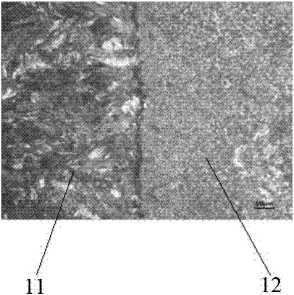
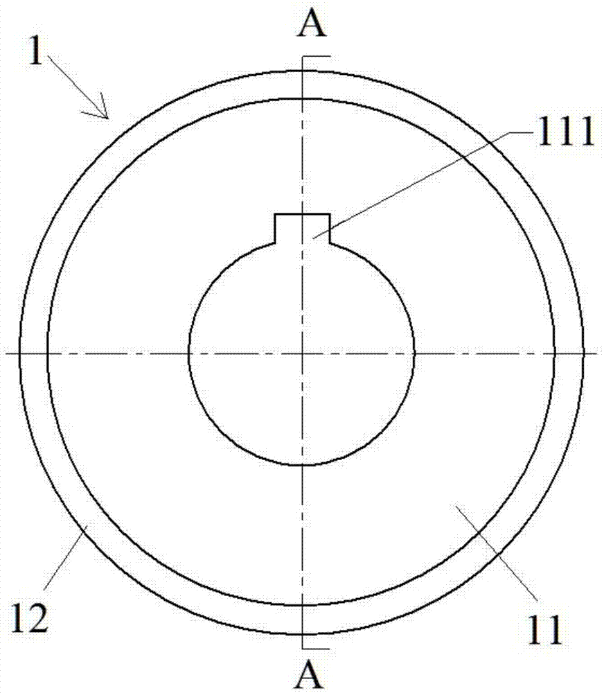
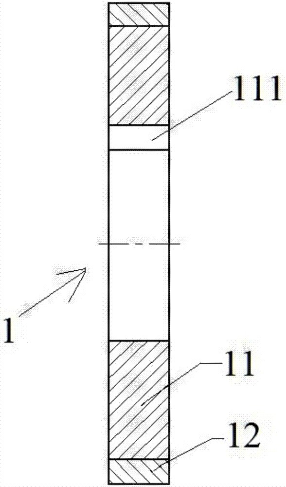
[0036] like figure 1 and 2As shown, the blade 1 comprises a blade base 11 and a blade layer 12 . Wherein, the blade base 11 is an annular cake body, and the inner side wall of the annular cake body is provided with an assembly keyway 111 for installation and positioning; the blade layer 12 fits and covers the outer side wall of the blade base body 11 . Preferably, the base body 11 of the blade can be made of 35CrMo steel, so that the prepared blade can withstand impact, bending and high load under complex force conditions, thereby prolonging the service life of the blade.

[0037] like image 3 As sho...

Embodiment 1

[0047] Prepare a blade base body 11 with an outer diameter of 300 mm, and coat the blade base body 11 with a blade sheath 2, and the powder particle size of the alloy powder 3 filled into the blade sheath 2 is 50 μm, and the chemical composition and each chemical composition The weight percentages are: 2.1% carbon, 5.0% chromium, 1.5% molybdenum, 10.0% vanadium, 0.8% silicon, 0.5% manganese, and the rest is Fe. After the filling of the alloy powder 3 is completed, the alloy powder 3 is firstly vibrated, and the top cover 26 is placed on the top of the powder filling channel 25, and sealed and connected by argon arc welding. Next, place the blade cover 2 with the blade matrix 11 and the alloy powder 3 built in it in a degassing furnace to heat and vacuumize it. When the temperature reaches 450° C. and the vacuum degree reaches 2×10 -3 Pa, keep the temperature and vacuum constant for 2 hours to complete the degassing and heat preservation treatment. Then, put the blade sheath 2...

Embodiment 2

[0050] Prepare a blade base body 11 with an outer diameter of 400mm, and coat the blade base body 11 with a blade sheath 2, and the powder particle size of the alloy powder 3 filled into the blade sheath 2 is 100 μm, and the chemical composition and each chemical composition The weight percentages are: 2.2% carbon, 4.5% chromium, 1.2% molybdenum, 9.0% vanadium, 1.0% silicon, 0.8% manganese, and the rest is Fe. After the filling of the alloy powder 3 is completed, the alloy powder 3 is firstly vibrated, and the top cover 26 is placed on the top of the powder filling channel 25, and sealed and connected by argon arc welding. Next, place the blade cover 2 with the blade matrix 11 and the alloy powder 3 built in it in a degassing furnace to heat and vacuumize it. When the temperature reaches 500°C and the vacuum degree reaches 2×10 -3 At Pa, keep the temperature and vacuum constant for 4 hours to complete the degassing and heat preservation treatment. Then, put the blade sheath 2...


PUM

PropertyMeasurementUnit
flexural strengthaaaaaaaaaa

Abstract

The invention relates to the field of preparation of mechanical blades and provides a blade of a disc shearing machine and further provides a preparation method of the blade of the disc shearing machine. The blade is used for shearing stainless steel and a high-strength steel plate and is high in cost performance. The preparation method of the blade of the disc shearing machine comprises the stepsthat a blade base body is prepared and wrapped with a blade sheath, the space between the outer side wall of the blade sheath and the outer side wall of the blade base body is filled with alloy powder through a powder filling channel in an annular cover plate located on the blade sheath, and a top cover is mounted on the powder filling channel after filling and vibrating compaction; the blade sheath internally provided with the blade base body and the alloy powder is placed in a degassing furnace, vacuumizing and degassing heat preservation are conducted, then the blade sheath is placed in ahot isostatic pressure furnace to be subjected to hot isostatic pressure treatment, and thus a blade edge layer is formed; and the blade sheath is removed through machining, thus a blade blank is obtained, then annealed, quenched and tempered, and the blade is obtained through finish machining. The blade prepared through the method is uniform in edge thickness, resistant to abrasion, long in service life, low in cost and high in cost performance.

Description

technical field [0001] The invention relates to the field of preparation of mechanical blades, in particular to a disc shear blade used for stripping or trimming steel plates such as stainless steel and high-strength steel and a preparation method thereof. Background technique [0002] With the rapid development of industries such as high-speed rail, nuclear power, construction, petroleum, automobiles, and home appliances, the proportion of stainless steel and high-strength steel plates used continues to increase, and stainless steel and high-strength steel plates are prone to sticking during shearing due to their high Ni content. steel. Due to the large internal stress, low plasticity and toughness of high-strength steel plates, when using disc shears to shear high-strength steel plates, the cutting edges of the disc shears are prone to flanging, chipping, uneven wear and Passivation speed and other issues. Therefore, in order to complete the shearing work, the shearing o...

Claims


Application Information

Patent Timeline
Patent Type & Authority Applications(China)
IPC IPC(8): B22F7/08B22F5/00B23D35/00
Inventor 车洪艳厉鑫洋刘文彬王铁军董浩陈伟
Owner ADVANCED TECHNOLOGY & MATERIALS CO LTD
Why Eureka
Try Eureka