Fabrication device and fabrication method of substrate surface light trapping structure

A light-trapping structure and technology for preparing devices, which is applied in the field of solar energy, can solve the problems of limited efficiency improvement, poor light-trapping effect, and high manufacturing cost, and achieve anti-reflection, improve light utilization, and increase light-receiving area Effect

Inactive Publication Date: 2018-02-02
北京旭日龙腾新能源科技有限公司
View PDF3 Cites 6 Cited by
  • Summary
  • Abstract
  • Description
  • Claims
  • Application Information

AI Technical Summary

Problems solved by technology

However, the current surface light-trapping structures each have their own limitations, either cannot be mass-produced (such as laser etching, etc.), or the preparation solution contains heavy metals, etc., so the preparation cost is high and the light-trapping effect is not good; and the existing The method can only fabricate light-trapping structures on the order of millimeters or even microns, so the efficiency improvement effect is limited

Method used


Image

  • Fabrication device and fabrication method of substrate surface light trapping structure
  • Fabrication device and fabrication method of substrate surface light trapping structure
  • Fabrication device and fabrication method of substrate surface light trapping structure

Examples


preparation example Construction

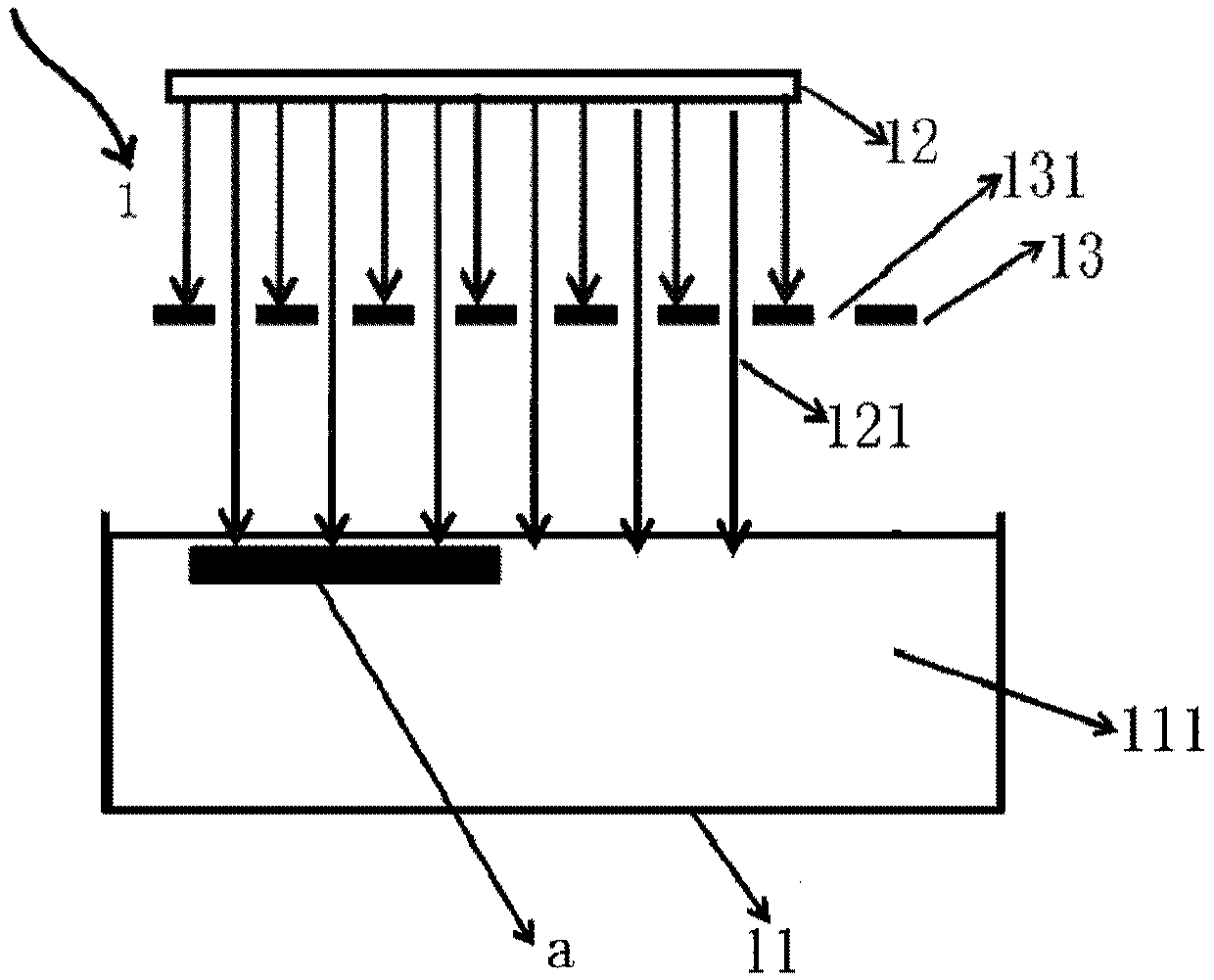
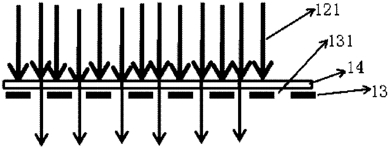
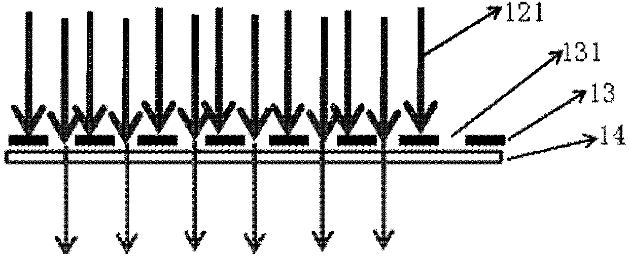
[0057] based on Figure 9 The preparation device of the light-trapping structure on the surface of the substrate, the present invention also proposes a preparation method of the light-trapping structure on the surface of the substrate, using the above-mentioned preparation device of the light-trapping structure on the surface of the substrate, comprising the following steps: Step 1. Catalytic light, the catalytic light is injected into the corrosion tank through the pores of the light-transmitting plate; step 2, the corrosion liquid in the corrosion tank, under the action of catalytic light, corrodes the substrate placed in the corrosion tank, forming Light-trapping structure; step 3, the mechanical arm cooperates with the insertion machine to move the substrate with the light-trapping structure on the surface to the acid modification tank, and the acid modification solution therein modifies the surface of the light-trapping structure; step 4, the mechanical arm cooperates with...

Embodiment

[0075] Such as Figure 11 It is a schematic diagram of the light-trapping structure manufacturing equipment and its supporting process proposed in this embodiment. This figure is a schematic diagram of chain equipment.

[0076] The manufacturing equipment of the present embodiment has six tanks: respectively chain type corrosion tank body 701 and tank type corrosion tank body 702 and 703 three corrosion tank bodies; 705 and 706). These tanks are Figure 11 Arranged in a way that constitutes the corrosion body of the entire device. Wherein above the tank body of 701, there is a surface light source 707 and a light-transmitting plate 708 (on the light-transmitting plate is a light-transmitting small hole 708a). The light passes through the small light-transmitting hole 708 a on the light-transmitting plate 708 , and shines on the battery sheet 8 in the corrosion tank 701 . The battery sheet 8 is placed on the top of the roller 701a in the tank. When the roller 701a rotates...


PUM


Abstract

The invention relates to a fabrication device and fabrication method of a substrate surface light trapping structure. The fabrication device of the substrate surface light trapping structure comprisesa corrosion groove, a light source and a light transmitting plate, wherein the corrosion groove is used for loading a corrosion liquid and a substrate to be corroded, the light source is used for emitting catalytic light, the light transmitting plate is arranged above the corrosion groove, periodic gaps are formed in the light transmitting plate and are used for enabling the catalytic light to irradiate the corrosion groove, and a substrate surface is corroded by the corrosion liquid the effect of the catalytic light to obtain the light trapping structure. Photocatalysis is used for corrosionreaction, mass production of the light trapping structure can be achieved compared with a traditional light trapping structure mask, a nanoscale light trapping structure can be fabricated compared with a traditional scratching or simple corrosion method, the light receiving area can be greatly expanded, reflection resistance is effectively achieved, so that technical inspiration is provided for improving efficiency of a solar cell and a photoelectric detector.

Description

technical field [0001] The invention belongs to the technical field of solar energy, and more specifically relates to a preparation device and a preparation method of a light-trapping structure on the surface of a substrate. Background technique [0002] The photovoltaic industry is developing rapidly, and more than 90% of the products in the photovoltaic market are crystalline silicon solar cells. However, continuous efficiency improvement and cost reduction are the biggest problems at present. Some new battery technologies, such as N-type double-sided battery technology, N-type heterojunction battery technology, P-type emitter passivated rear contact (PERC) battery technology, diamond wire-cut polysilicon battery technology, etc., have emerged to meet future market demands. development needs. [0003] Although there are many methods and technical means to improve battery efficiency, the improvement effect is not obvious, and there are defects of complex design and harsh ...

Claims


Application Information

Patent Timeline
Patent Type & Authority Applications(China)
IPC IPC(8): H01L21/67H01L31/0236
CPCY02E10/50H01L21/67086H01L31/02363
Inventor 张芸贾旭涛贾瑞
Owner 北京旭日龙腾新能源科技有限公司
Why Eureka
Try Eureka