A kind of preparation method of u-mo-zr alloy

A u-mo-zr, alloy technology, applied in the field of U-Mo-Zr alloy preparation, can solve the problems of long process cycle, material loss and impurity increase, achieve high alloy purity, improve alloy uniformity, improve Effect of Alloy Purity

Active Publication Date: 2019-04-16
MATERIAL INST OF CHINA ACADEMY OF ENG PHYSICS
View PDF2 Cites 0 Cited by
  • Summary
  • Abstract
  • Description
  • Claims
  • Application Information

AI Technical Summary

Problems solved by technology

[0006] The purpose of the present invention is to: for the preparation of uranium-molybdenum-zirconium ternary alloys by methods such as vacuum induction melting or arc melting, multiple repeated meltings are required, which not only has a long process cycle, but also increases the risk of material loss and impurities. Problem, provide a kind of preparation method of U-Mo-Zr alloy

Method used


Image

  • A kind of preparation method of u-mo-zr alloy
  • A kind of preparation method of u-mo-zr alloy
  • A kind of preparation method of u-mo-zr alloy

Examples


Embodiment 1

[0054] Example 1 Preparation of U-8Mo-2Zr alloy

[0055] (1) U-8Mo alloy was prepared by one-time alloying in graphite crucible

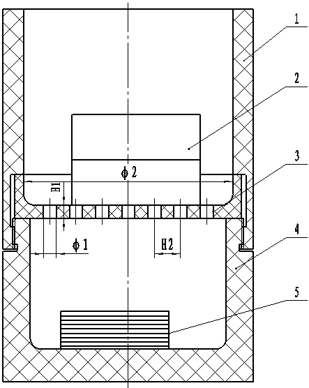
[0056] The inner surface of the graphite crucible, the outer surface of the graphite sieve plate and the sieve holes are plasma-sprayed with calcium zirconate coating. Such as figure 1 As shown, the proportion of molybdenum raw material is adjusted to 8.3wt.%. Molybdenum wire is placed under the graphite sieve plate, uranium ingots are placed on the graphite sieve plate, the diameter of the graphite sieve plate is 5mm, and the center line of the adjacent sieve The distance between them is 10mm, the sieve holes are equidistantly distributed, and the thickness of the sieve plate is 8mm. After the raw materials are placed, the furnace is vacuumed to 5*10 -2 After Pa, the power is turned on. After the material is completely melted, it is kept at 1500°C for 30 minutes, and the temperature is lowered to 1200°C at a rate of 10°C / min. After that, the pow...

Embodiment 2

[0061] Example 2 Preparation of U-2Mo-8Zr alloy

[0062] (1) Prepare U-2Mo alloy by one-time alloying in graphite crucible

[0063] The inner surface of the graphite crucible, the outer surface of the graphite sieve plate and the sieve holes are plasma-sprayed with calcium zirconate coating. Such as figure 1 As shown, the proportion of molybdenum raw material is adjusted to 2.2wt.%. Molybdenum wire is placed under the graphite sieve plate, uranium ingots are placed on the graphite sieve plate, the diameter of the graphite sieve plate is 5mm, and the center line of the adjacent sieve The distance between them is 10mm, the sieve holes are equidistantly distributed, and the thickness of the sieve plate is 8mm. After the raw materials are placed, the furnace is vacuumed to 5*10 -2 After Pa, the power is turned on, and after the material is completely melted, it is kept at 1450°C for 25 minutes, and the temperature is lowered to 1200°C at a rate of 12°C / min.

[0064] (2) Using ...


PUM

PropertyMeasurementUnit
thicknessaaaaaaaaaa

Abstract

The invention discloses a preparing method for a U-Mo-Zr alloy. The preparing method comprises the following steps of graphite crucible primary alloying, graphite sieve plate ingot leaking and ceramiccrucible secondary alloying. A primary ingot of a binary alloy is prepared through graphite crucible primary alloying firstly, then, a binary alloy ingot with few inclusions is obtained through ingotleaking in a graphite sieve plate, then, a tertiary alloy is prepared through ceramic crucible secondary alloying, and finally, the needed U-Mo-Zr alloy is obtained. In the preparing method, the graphite sieve plate is additionally arranged for conducting primary alloying, ceramic crucible secondary alloying and other optimization technology lines, technology parameters are reasonably controlled,and dissolving and diffusing of alloy elements are more sufficient. Meanwhile, the inclusions are further controlled through ingot leaking, ceramic crucible smelting is adopted for secondary alloying, the alloy purity is greatly improved, and the alloy uniformity is improved. In addition, the high-quality U-Mo-Zr alloy can be obtained by adopting three procedures, and the period of the preparingtechnology is short.

Description

technical field [0001] The invention relates to the field of alloy preparation, especially the field of metal smelting and forming, and specifically relates to a method for preparing a U-Mo-Zr alloy. Background technique [0002] Adding a small amount of zirconium or molybdenum to uranium can prepare fine-grained alloys with good dimensional stability, and uranium-zirconium or uranium-molybdenum alloys have very important application values ​​in the field of nuclear reactors. However, alloying elements have high melting points, and their density is quite different from that of uranium. It is difficult to ensure sufficient dissolution of zirconium or molybdenum during the smelting process, which seriously restricts the uniformity of alloy composition. In addition, during the smelting process, zirconium or molybdenum easily reacts with carbon, nitrogen and other elements to form carbon and nitrogen inclusions, and the aggregation of inclusions is one of the reasons for the com...

Claims


Application Information

Patent Timeline
Patent Type & Authority Patents(China)
IPC IPC(8): C22C43/00C22C1/02
CPCC22C1/02C22C43/00
Inventor 曾钢苏斌陈道明唐清富税毅龙波
Owner MATERIAL INST OF CHINA ACADEMY OF ENG PHYSICS
Why Eureka
Try Eureka