
Energy-saving and environment-friendly boiler for thermal power plant

An energy saving, environmental protection, thermal power plant technology, applied in steam boilers, feed water heaters, preheating, etc., can solve the problems of waste, pollution, energy conversion efficiency waste, etc., and achieve the effect of reducing the degree of pollution and saving energy

Inactive Publication Date: 2018-02-23
东莞旺科知识产权运营有限公司
View PDF0 Cites 1 Cited by
  • Summary
  • Abstract
  • Description
  • Claims
  • Application Information

AI Technical Summary

Problems solved by technology

[0002] Thermal power generation is the main power generation method in my country. Its basic production process is: when the fuel is burned, water is heated to generate steam, and the chemical energy of the fuel is converted into heat energy. The steam pressure drives the steam turbine to rotate, and the heat energy is converted into mechanical energy, and then the steam turbine drives the generator. Rotate to convert mechanical energy into electrical energy. After multiple energy conversions, it usually causes great waste due to energy conversion efficiency, especially the conversion of thermal energy into mechanical energy. The efficiency is usually below 40%, which will cause great waste.
[0003] my country is rich in coal resources, so the commonly used thermal power boilers are coal-fired boilers, but the direct combustion of coal will cause serious pollution, and in some areas of my country, the coal sulfur and nitrogen content exceeds the standard, and the exhaust gas emitted by coal-fired power generation contains a large amount of sulfides, nitrogen oxides

Method used


Image

  • Energy-saving and environment-friendly boiler for thermal power plant
  • Energy-saving and environment-friendly boiler for thermal power plant
  • Energy-saving and environment-friendly boiler for thermal power plant

Examples


Embodiment Construction

[0017] The technical solutions in the embodiments of the present invention will be clearly and completely described below with reference to the accompanying drawings in the embodiments of the present invention. Obviously, the described embodiments are only a part of the embodiments of the present invention, but not all of the embodiments. Based on the embodiments of the present invention, all other embodiments obtained by those of ordinary skill in the art without creative efforts shall fall within the protection scope of the present invention.

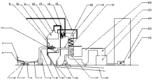
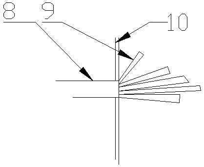
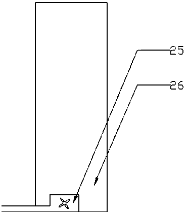
[0018] see Figure 1~3 , In the embodiment of the present invention, an energy-saving and environmentally friendly boiler for thermal power plants includes a coal inlet 1, a coal inlet pipe 2, a blower 3, a blower pipe 4, a coal mill 5, a powder discharge machine 6, a powder blowing pipe 7, Powder discharge pipe 8, multi-head pulverized coal outlet 9, boiler wall 10, evaporation chamber 11, steam drum boiler 12, steam pipe 13, superhe...


PUM


Abstract

The invention discloses an energy-saving and environment-friendly boiler for a thermal power plant, which comprises a coal inlet, a coal inlet pipe, a blower, a blast pipe, a coal mill, a pulverizer, a pulverizer blowing pipe, a pulverized discharge pipe, a multi-head pulverized coal outlet, and a boiler. Wall, evaporation chamber, drum boiler, steam pipe, superheater, water inlet pipe, economizer, air preheater, air inlet pipe, air outlet, blower, exhaust gas pipe, dust collector, desulfurization chamber, nitrogen removal chamber, Exhaust gas turbine, chimney, slag blowing outlet, slag outlet and slag discharge ditch, the coal inlet is connected to the coal inlet pipe, the coal inlet pipe is connected to the coal mill, the bottom of the coal mill is connected to the blast pipe, and the drum The air duct is connected to the blower, the position of the pulverizer relative to the blast pipe is connected to the powder blowing pipe, the powder blowing pipe is connected to the powder discharger, and the powder discharger is connected to the powder discharge pipe. The temperature of the waste gas is lowered while the temperature of the inlet water and the intake air is increased, which saves energy, and the waste gas is treated with dust removal, desulfurization and nitrogen removal to reduce the degree of waste gas pollution.

Description

technical field [0001] The invention relates to thermal power generation equipment, in particular to an energy-saving and environment-friendly boiler for thermal power plants. Background technique [0002] Thermal power is the main power generation method in my country. Its basic production process is: when fuel is burned, water is heated to generate steam, the chemical energy of the fuel is converted into heat energy, the steam pressure drives the steam turbine to rotate, and the heat energy is converted into mechanical energy, and then the steam turbine drives the generator. Rotation converts mechanical energy into electrical energy. After many times of energy conversion, it usually causes great waste due to the energy conversion efficiency, especially the conversion of thermal energy into mechanical energy. The efficiency is usually below 40%, which will cause great waste. [0003] my country is rich in coal resources, so the commonly used thermal power boilers are coal-fi...

Claims


Application Information

Patent Timeline
IPC IPC(8): F22B31/08F22D1/24F23J1/00F23J15/02
CPCF22B31/08F22D1/24F23J1/00F23J15/022
Inventor 张征张玉环吴美
Owner 东莞旺科知识产权运营有限公司
Learn More