Dry type urea pyrolysis ammonia preparation system and method

A urea and pyrolysis technology, applied in the field of dry urea pyrolysis ammonia production system, can solve the problems of increased system energy consumption, low reliability, excessive water supply, etc., to reduce operating costs, avoid pipeline corrosion, The effect of guaranteed conversion rate

Pending Publication Date: 2018-02-27
HUADIAN ELECTRIC POWER SCI INST CO LTD
View PDF9 Cites 5 Cited by
  • Summary
  • Abstract
  • Description
  • Claims
  • Application Information

AI Technical Summary

Problems solved by technology

Because urea solution is easy to crystallize and has corrosive characteristics, the mass concentration of urea solution generally configured is low, which will inevitably lead to excessive water supply and increased power consumption of electric heaters
[0003] In the prior art, CN103950953A discloses a device and method for producing ammonia by pyrolysis of urea for flue gas denitrification, which uses dry urea and atomized water droplets for pyrolysis to produce ammonia, but the entry of atomized water droplets into the pyrolysis furnace will increase the system capacity. Energy consumption and it is extremely difficult to fully mix the atomized water droplets and urea, and the conversion rate of urea is unstable
[0004] CN101870480A discloses a device for producing ammonia by solid dry pyrolysis of urea, which generates ammonia-containing mixed gas by reacting urea particles with high-temperature flue gas, wherein the high-temperature flue gas is driven by high-temperature fan booster, but the high-temperature fan has high cost and short service life , low reliability

Method used


Image

  • Dry type urea pyrolysis ammonia preparation system and method

Examples


Embodiment Construction

[0019] The present invention will be further described in detail below in conjunction with the accompanying drawings and examples. The following examples are explanations of the present invention and the present invention is not limited to the following examples.

[0020] Example.

[0021] see figure 1 .

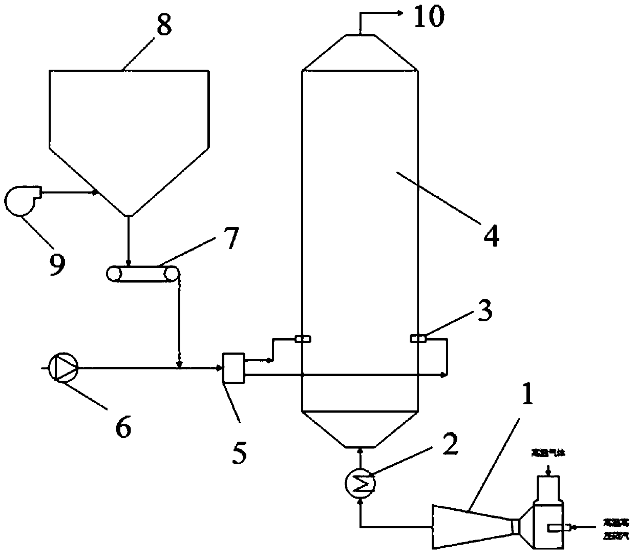
[0022] This embodiment is a dry-type urea pyrolysis ammonia production system, including an ejector 1, an electric heater 2, a powder supply port 3, a pyrolysis furnace 4, a distributor 5, a Roots blower 6, and a metering feeder 7 , urea storage bin 8 and fluidization fan 9.

[0023] The inlet of the ejector 1 is connected with the high-temperature and high-pressure steam pipe and the high-temperature gas pipe respectively, the outlet of the ejector 1 is connected with the inlet of the electric heater 2 , and the outlet of the electric heater 2 is connected with the bottom of the pyrolysis furnace 4 .

[0024] The outlet of the fluidization fan 9 is connected with the bot...


PUM


Abstract

The invention relates to a dry type urea pyrolysis ammonia preparation system and a dry type urea pyrolysis ammonia preparation method. The dry type urea pyrolysis ammonia preparation system is characterized by comprising an ejector, an electric heater, a power feeding opening, a pyrolyzing furnace, a distributor, a Roots blower, a metering feeding machine, a urea storage cabin and a fluidizationfan; an outlet of the ejector is connected with an inlet of the electric heater; an outlet of the electric heater is communicated with the bottom of the pyrolyzing furnace; an outlet of the fluidization fan is communicated with the bottom of the urea storage cabin; an outlet of the urea storage cabin is communicated with the metering feeding machine; a discharging opening of the metering feeding machine and an outlet of the Roots blower communicate with an inlet of the distributor after being merged; an outlet of the distributor is communicated with an inlet of the power feeding opening; an outlet of the power feeding opening is formed in the pyrolyzing furnace. According to the dry type urea pyrolysis ammonia preparation system and the dry type urea pyrolysis ammonia preparation method, urea solution is replaced by adopting urea powder; the system is simplified; the investment is reduced; pipeline corrosion and crystallization are avoided; high-temperature gas is pressurized by ejecting high-temperature high-pressure vapour, so that the system is energy-saving and reliable; meanwhile, water vapour and gas can be mixed uniformly, so that the conversion rate of urea pyrolysis is ensured.

Description

technical field [0001] The invention belongs to the fields of industrial waste gas treatment, environmental protection and energy, and in particular relates to a dry-type urea pyrolysis ammonia production system and method. Background technique [0002] With the increasingly stringent safety production requirements, urea has become a reliable substitute for liquid ammonia as a reductant for SCR flue gas denitrification in thermal power plants due to its safe and convenient transportation and storage and the characteristics of being harmless to the environment. Using urea as a reducing agent, it is necessary to decompose urea into NH by heating 3 and CO 2 . There are two processes of urea ammonia production, pyrolysis and hydrolysis. Among them, pyrolysis is widely used due to the characteristics of small operation and maintenance engineering, low investment and no secondary pollution. The chemical reaction formula of urea pyrolysis is CO(NH 2 ) 2 +H 2 O→2NH 3 +CO 2 ,...

Claims


Application Information

Patent Timeline
Patent Type & Authority Applications(China)
IPC IPC(8): C01C1/08
CPCC01C1/086Y02P20/10
Inventor 裴煜坤朱跃江建平徐克涛冯前伟李壮
Owner HUADIAN ELECTRIC POWER SCI INST CO LTD
Why Eureka
Try Eureka