Purification system for mixture of micro-particles and volatile organic gas

A volatile organic and purification system technology, which is applied in the field of mixture purification system, can solve the problems of low chemical activity of benzene series, no good effect of VOCs, troublesome and difficult regeneration of adsorbents, etc., so as to reduce equipment cost investment and share The effect of small area, simple installation and operation

Inactive Publication Date: 2018-04-20
JIANGSU UNIV OF TECH
View PDF5 Cites 15 Cited by
  • Summary
  • Abstract
  • Description
  • Claims
  • Application Information

AI Technical Summary

Problems solved by technology

The utility model patent with publication number 203842462U discloses "a gas purification device for coating production", which mainly adopts the method of "liquid absorption + filtration". The technical solution of the above patent has a good removal effect on particulate matter, but has no effect on VOCs. very good result
[0004] In addition, the absorption method is widely used to treat organic waste gas such as petrochemical industry. Due to the low chemical activity of benzene series in the waste gas, physical absorption method is usually used. The key and difficulty of the technology lies in the selection of absorbent; the adsorption method usually uses activated carbon as the adsorption method to purify VOCs. The purification efficiency is high, but the discarded adsorbent needs to be regenerated or treated as a hazardous waste, which brings additional treatment costs; and the regeneration of the adsorbent is also very troublesome and difficult

Method used


Image

  • Purification system for mixture of micro-particles and volatile organic gas
  • Purification system for mixture of micro-particles and volatile organic gas
  • Purification system for mixture of micro-particles and volatile organic gas

Examples


Embodiment Construction

[0048] The present invention is described in further detail now in conjunction with accompanying drawing. These drawings are all simplified schematic diagrams, which only illustrate the basic structure of the present invention in a schematic manner, so they only show the configurations related to the present invention.

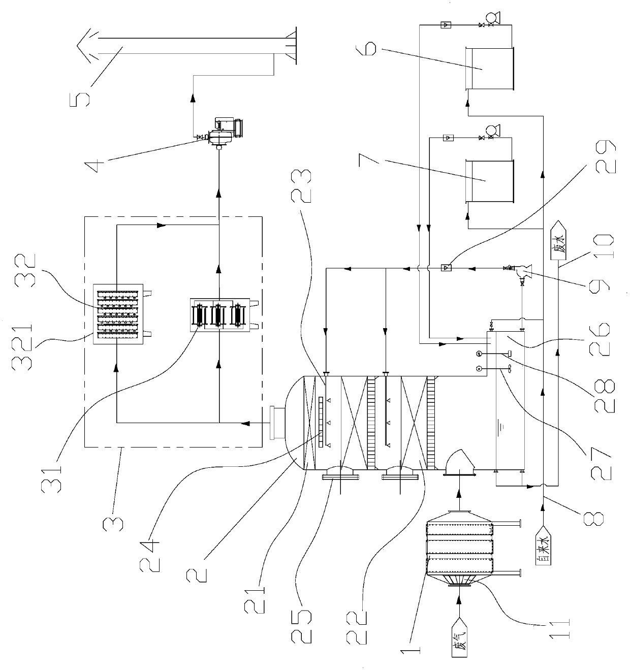
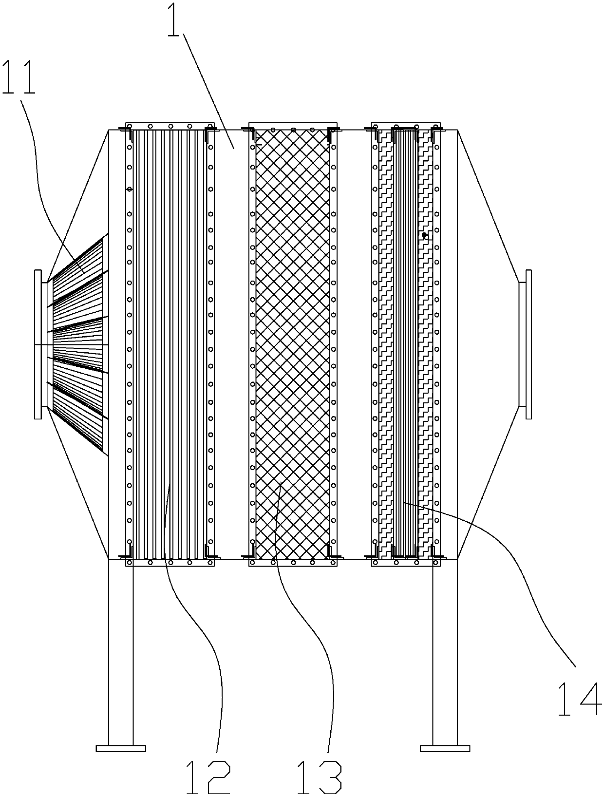
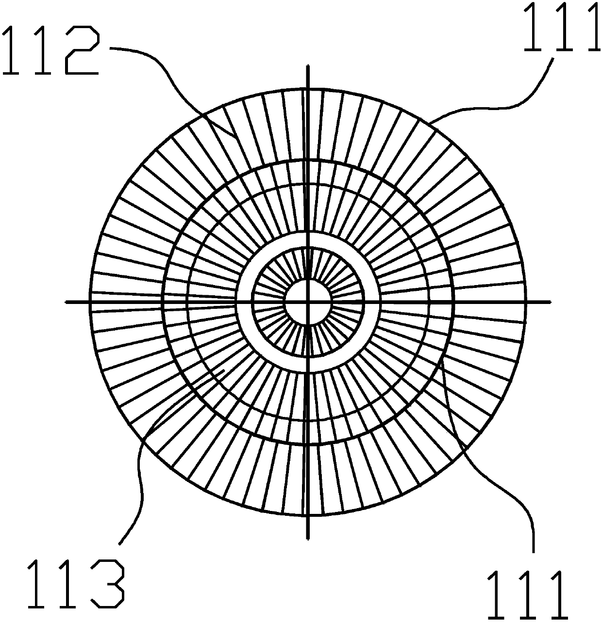
[0049] Such as Figure 1-Figure 6 A specific embodiment of the purification system for a mixture of microparticles and volatile organic gases of the present invention is shown, which includes a particulate filter 1, a wet oxidation reaction tower 2, a photocatalytic reaction module 3, and a pipeline connected in sequence. Fan 4 and flue gas discharge device 5; Photocatalytic reaction module 3 is the photocatalytic reactor 31 of single photocatalytic reactor 31 or multiple parallel arrangements; Photocatalytic reactor 31 comprises electrodeless ultraviolet lamp 311, quartz casing 312 and outer Cylinder 313, electrodeless ultraviolet lamp 311 includes inner ele...


PUM


Abstract

The invention belongs to the technical field of exhaust gas purification and particularly relates to a purification system for a mixture of micro-particles and volatile organic gas. The purification system comprises a particulate filter, a wet oxidation reaction tower, a photocatalytic reaction module, a fan and a flue gas discharge device and the above parts are orderly communicated through pipes. The photocatalytic reaction module comprises one or more photocatalytic reactors connected in parallel. The photocatalytic reactor comprises an electrodeless UV lamp, a quartz casing pipe and an outer cylinder. The electrodeless UV lamp comprises an inner electrode, an outer electrode and a variable high voltage power supply. Each inner wall of the outer cylinder is uniformly and fixedly provided with catalyst glass slides. The catalyst glass slide is uniformly coated with a catalyst. Through synergism purification of the three treatment methods, exhaust gas is completely decomposed. The adjustable variable high-voltage power supply can change low-pressure mixed gas so that ultraviolet lights with different wavelengths are obtained, different exhaust gas is degraded and activated carbonadsorption is avoided. The purification system has high purification efficiency, realizes a low cost and is easy to use.

Description

technical field [0001] The invention belongs to the technical field of waste gas purification, and in particular relates to a purification system for the mixture of microparticles and volatile organic gases. Background technique [0002] Volatile organic compounds (VOCs) are one of the most important pollutants in the air. Many VOCs are highly toxic and are odorous substances, which pose serious hazards to human health. VOCs substances can also produce photochemical smog with NOx emitted by automobiles and factories to form ozone and formaldehyde, etc. Therefore, VOCs form secondary organic aerosol particles and O 3 It is an important precursor of atmospheric pollution and the key to the formation of haze. VOCs can also affect the earth's radiation balance, reduce atmospheric visibility, and seriously endanger human health and the ecological environment. [0003] Some industries, such as petroleum industry, chemical industry, etc., will produce a large amount of exhaust ga...

Claims


Application Information

Patent Timeline
Patent Type & Authority Applications(China)
IPC IPC(8): B01D53/75B01D53/74B01D53/78B01D53/86B01D53/72B01D46/00B01D46/12B01D46/30
CPCB01D46/12B01D46/30B01D53/74B01D53/75B01D53/78B01D53/8668B01D2255/2092B01D2255/702B01D2255/50B01D2251/106B01D2251/108B01D2255/20707B01D2255/802B01D2257/708B01D2257/7027B01D46/62
Inventor 叶招莲瞿珍秀许澎马帅帅顾爱军
Owner JIANGSU UNIV OF TECH
Why Eureka
Try Eureka