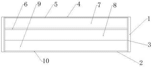
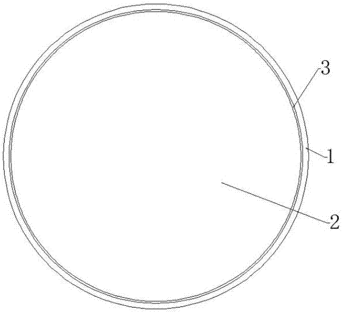
Crystal coated near-infrared low-pass filter and manufacturing method
A technology of low-pass filter and manufacturing method, applied in instruments, filters, applications, etc., can solve the problem of easy falling off of the ink layer, and achieve the effect of good infrared absorption effect, uniform ink coating and good adhesion effect.
- Summary
- Abstract
- Description
- Claims
- Application Information
AI Technical Summary
Problems solved by technology
Method used
Image
Examples
Embodiment 1
[0024] A preparation method of infrared absorbing ink for crystal, comprising the following steps:
[0025] S1. In parts by weight, mix 13 parts of n-propanol, 52 parts of N,N-dimethylformamide, and 35 parts of ethylene glycol ether to obtain a solvent, then mix 5 parts of copper phthalocyanine sulfonic acid, 2 parts of phthalocyanine Magnesium cyanine and 2.5 parts of vanadyl naphthalocyanine were added to the solvent, and after ultrasonic dispersion, 0.3 part of ethoxylamine was added, and the infrared absorption solution was obtained after stirring at 1300 rpm at 50 ° C for 15 minutes;
[0026] S2. In parts by weight, add 16 parts of acrylate copolymer to the infrared absorbing solution prepared in S1, mix at room temperature at a speed of 1800 rpm, then pass nitrogen gas for 20 minutes, then add 0.15 parts of silane coupling agent KH570, Heat at 60°C for 28 minutes, then cool down to normal temperature to obtain infrared absorbing ink.
[0027] The preparation method of t...
Embodiment 2
[0029] A preparation method of infrared absorbing ink for crystal, comprising the following steps:
[0030] S1. In parts by weight, mix 10 parts of n-propanol, 57 parts of N,N-dimethylformamide, and 38 parts of ethylene glycol ether to obtain a solvent, then mix 3 parts of copper phthalocyanine sulfonic acid, 2.5 parts of phthalocyanine Magnesium cyanine and 3 parts of vanadyl naphthalocyanine were added to the solvent, and after ultrasonic dispersion, 0.2 parts of ethoxylamine was added, and stirring was continued at 52°C at a speed of 1500 rpm, and an infrared absorption solution was obtained after stirring for 10 minutes;
[0031] S2. In parts by weight, add 17 parts of acrylate copolymer to the infrared absorbing solution prepared in S1, mix at room temperature at a speed of 2000 rpm, then pass nitrogen gas for 20 minutes, then add 0.13 parts of silane coupling agent KH570, Heat at 61°C for 30 minutes, then cool down to room temperature to obtain an infrared absorbing ink....
Embodiment 3
[0034] A preparation method of infrared absorbing ink for crystal, comprising the following steps:
[0035] S1. In parts by weight, mix 12 parts of n-propanol, 61 parts of N,N-dimethylformamide, and 33 parts of ethylene glycol ether to obtain a solvent, then mix 4 parts of copper phthalocyanine sulfonic acid, 3 parts of phthalocyanine Magnesium cyanine and 2 parts of vanadyl naphthalocyanine were added to the solvent, and after ultrasonic dispersion, 0.25 parts of ethoxylamine was added, and stirring was continued at 55°C at a speed of 1200 rpm, and an infrared absorption solution was obtained after stirring for 14 minutes;
[0036] S2. In parts by weight, add 19 parts of acrylate copolymer to the infrared absorbing solution prepared in S1, mix at room temperature at a speed of 1500 rpm, then pass nitrogen gas for 20 minutes, then add 0.14 parts of silane coupling agent KH570, Heat at 61°C for 30 minutes, then cool down to room temperature to obtain an infrared absorbing ink. ...
PUM
 Abstract
Description
Claims
Application Information
 - R&D
- Intellectual Property
- Life Sciences
- Materials
- Tech Scout
- Unparalleled Data Quality
- Higher Quality Content
- 60% Fewer Hallucinations
Browse by: Latest US Patents, China's latest patents, Technical Efficacy Thesaurus, Application Domain, Technology Topic, Popular Technical Reports.
© 2025 PatSnap. All rights reserved.Legal|Privacy policy|Modern Slavery Act Transparency Statement|Sitemap|About US| Contact US: help@patsnap.com


