
An online sunlight control coating tail gas treatment device and its treatment process

A technology for exhaust gas treatment and sunlight control, applied in the petroleum industry, combustion type, lighting and heating equipment, etc., to achieve the effect of improving service life, high purification efficiency and reducing operating costs

Active Publication Date: 2019-10-29
长兴旗滨玻璃有限公司
View PDF5 Cites 0 Cited by
  • Summary
  • Abstract
  • Description
  • Claims
  • Application Information

AI Technical Summary

Problems solved by technology

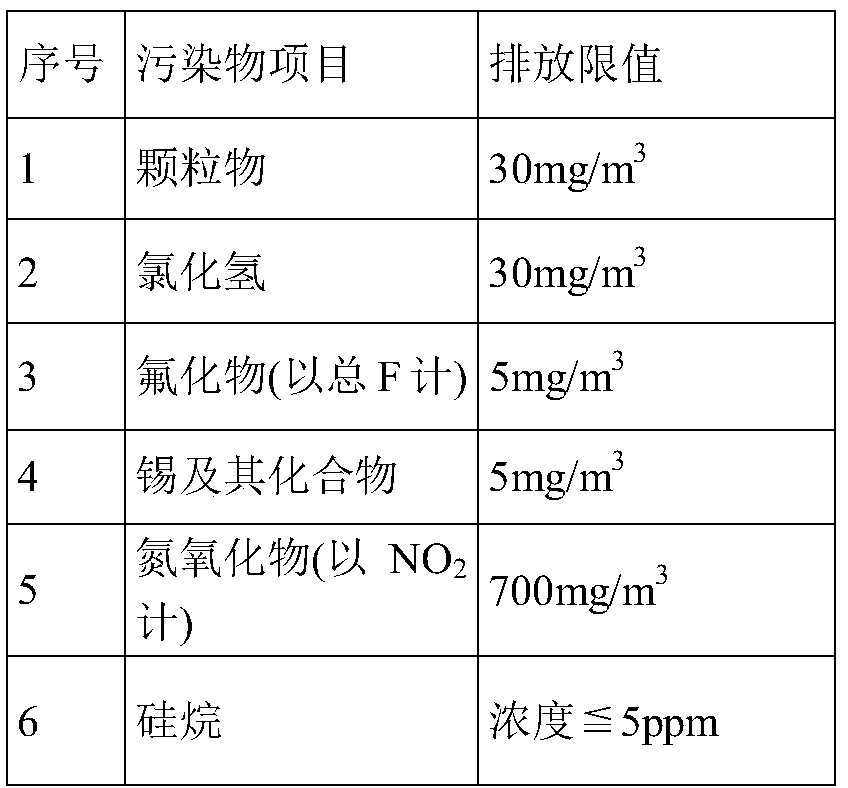
[0008] The purpose of the present invention is to achieve effective tail gas treatment, which is beneficial to environmental protection and at the same time meet the national exhaust gas discharge standards. The generated waste gas is treated, and the equipment meets or even lower than the national standard emission standard

Method used


Image

  • An online sunlight control coating tail gas treatment device and its treatment process
  • An online sunlight control coating tail gas treatment device and its treatment process
  • An online sunlight control coating tail gas treatment device and its treatment process

Examples


Embodiment 1

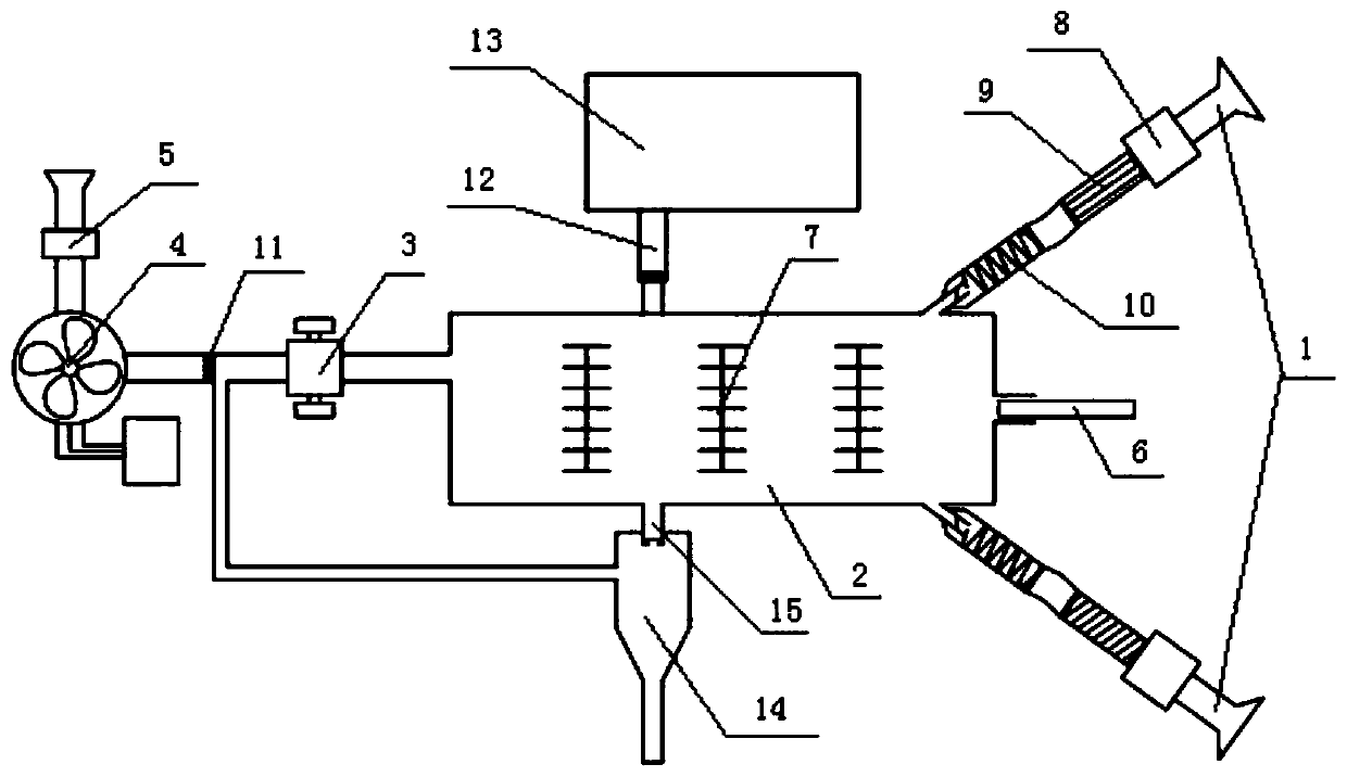
[0047] An online sunlight control coating tail gas treatment device, comprising two tail gas inlet pipes 1, a combustion chamber 2, an air outlet regulator 3, a frequency conversion fan 4, and a denitrification and desulfurization system 5, which are sequentially connected through connecting pipes. The tail gas inlet pipe 1 They are respectively arranged on both sides of the front end of the combustion chamber 2, and a diesel atomizing spray gun 6 is also provided in the middle of the same end of the combustion chamber 2 and the exhaust gas intake pipe 1. The interior of the combustion chamber 2 is provided with 3 combustion-supporting rods 7, and the combustion chamber 2 is long. One side of the edge is provided with an automatic pressure relief explosion-proof device 12 and a pressure relief pool 13, and the other side is provided with a dust removal hole 15 communicating with the dust removal equipment 14.

[0048] The pipeline between the exhaust gas intake pipeline 1 and t...

Embodiment 2

[0056] The device is the same as that of Example 1, except that a combustion-supporting improver is added to the diesel sprayed from the diesel atomizing spray gun 6, and the amount of the combustion-supporting improver is 1.2 g / L.

[0057] The combustion-supporting improver includes the following raw materials in parts by weight: 45 parts of rare earth oxygen storage materials, 42 parts of potassium permanganate, 51 parts of activated carbon, 10 parts of potassium perborate, 8 parts of dicyclopentadienyl iron and 12 parts of formazan ethyl ethyl ketone.

[0058] The rare earth oxygen storage material is Ce modified with Bi and Y elements 0.9 Zr 0.1 O oxygen storage material.

[0059] The combustion rod 7 is made of the following raw materials in parts by weight: 135 parts of manganese ore, 78 parts of waste incineration slag, 36 parts of lime mud, 4 parts of tin-doped indium oxide ITO and 7 parts of rosin pentaerythritol ester.

Embodiment 3

[0061] The device is the same as that in Example 1, except that a combustion-supporting improver is added to the diesel sprayed from the diesel atomizing spray gun 6, and the amount of the combustion-supporting improver is 1.5 g / L.

[0062] The combustion-supporting improver includes the following raw materials in parts by weight: 60 parts of rare earth oxygen storage materials, 45 parts of potassium permanganate, 55 parts of activated carbon, 12 parts of potassium perborate, 10 parts of dicyclopentadienyl iron and 15 parts of formazan ethyl ethyl ketone.

[0063] The rare earth oxygen storage material is Ce modified by Sr, Bi and Y elements 0.9 Zr 0.1 O oxygen storage material.

[0064] The combustion rod 7 is made of the following raw materials in parts by weight: 150 parts of manganese ore, 80 parts of waste incineration slag, 50 parts of lime mud, 5 parts of tin-doped indium oxide ITO and 8 parts of rosin pentaerythritol ester.


PUM


Abstract

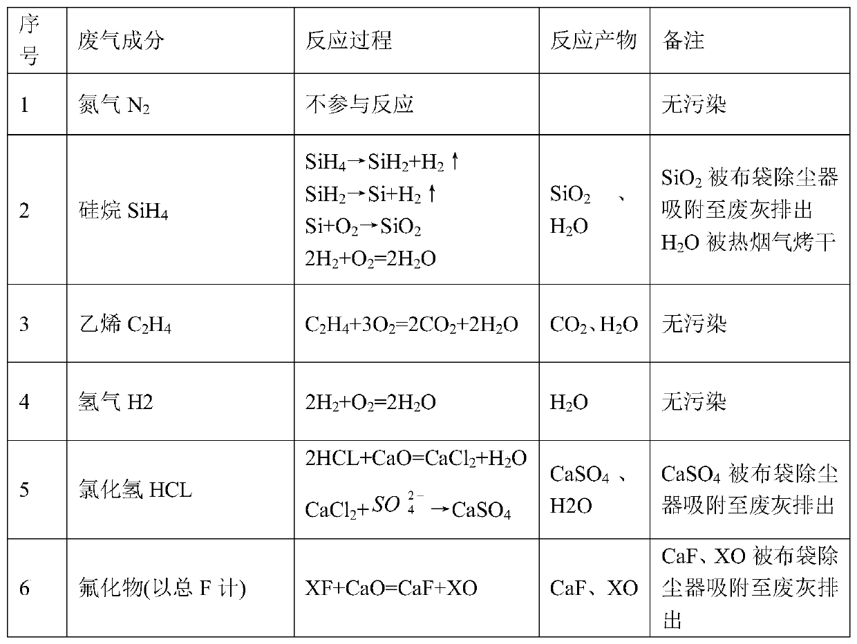
The invention relates to an online sunlight control coating tail gas treatment device and a process thereof. A modified device for operation, tail gas is mixed with nitrogen through a booster, the mixed gas enters a combustion chamber through a spiral air inlet pipe and is mixed with diesel sprayed by a diesel atomizing spray gun and then combustion is performed; exhaust gas generated after the performed passes through an air outlet regulator, a dust removing membrane, a frequency conversion fan and a denitrification desulfurization system and then is directly discharged; and dust generated bythe combustion enters a dedusting device through an ash removal hole. All the components in the coating exhaust gas can be effectively treated in the back end reaction, discharge up to the standard can be performed, and the amount of the coating exhaust gas is small is one ten thousandth of the amount of original chimney smoke, and particles generated by the reaction can be adsorbed by cloth bag,and nitrogen and water vapor and the like do not need to be treated. A desulfurization, denitration and dust removal device of an environmental protection system can effectively treat the tail gas, thereby avoiding secondary pollution; the operating cost is reduced, the service life of the device is prolonged, and purification efficiency is high.

Description

technical field [0001] The invention belongs to the field of glass industry and relates to tail gas treatment, in particular to an on-line sunlight control coating tail gas treatment device and a treatment process thereof, which have simple process, reduce operation cost, high purification efficiency and meet environmental protection requirements. Background technique [0002] Online solar control coated glass is a kind of coated glass with good control effect on sunlight, and this glass has good heat insulation performance. Under the condition of ensuring soft indoor lighting, it can effectively shield the solar radiation energy entering the room, avoid the warming effect, and save energy consumption of indoor cooling air conditioners; and has one-way perspective, and can be used as building door and window glass, curtain wall glass, It can also be used to make high-performance insulating glass, which has good energy-saving and decorative effects. Many modern high-end buil...

Claims


Application Information

Patent Timeline
Patent Type & Authority Patents(China)
IPC IPC(8): F23G7/06C10L1/12C10L1/30C10L1/185C10L10/00
CPCC10L1/1208C10L1/1233C10L1/1291C10L1/1857C10L1/305C10L10/00C10L2230/22F23G7/065
Inventor 訚清刘柏辉张青晏璕李海龙张慧玲袁丽娜杨雷叶泽龙
Owner 长兴旗滨玻璃有限公司
Learn More