Fuel cell stack flow field plate capable of supporting high-current density discharging

A fuel cell stack and high current density technology, which is applied to fuel cells, fuel cell components, circuits, etc., can solve problems such as increased contact resistance, no advantages, complex stack structure, etc., to reduce shape and position errors, The effect of improving consistency

Active Publication Date: 2018-06-15
TONGJI UNIV
View PDF12 Cites 10 Cited by
  • Summary
  • Abstract
  • Description
  • Claims
  • Application Information

AI Technical Summary

Problems solved by technology

Although it can achieve a weight reduction of 20% over traditional three-sheet metal panels, there is no advantage over two-sheet metal designs
The

Method used


Image

  • Fuel cell stack flow field plate capable of supporting high-current density discharging
  • Fuel cell stack flow field plate capable of supporting high-current density discharging
  • Fuel cell stack flow field plate capable of supporting high-current density discharging

Examples


Embodiment 1

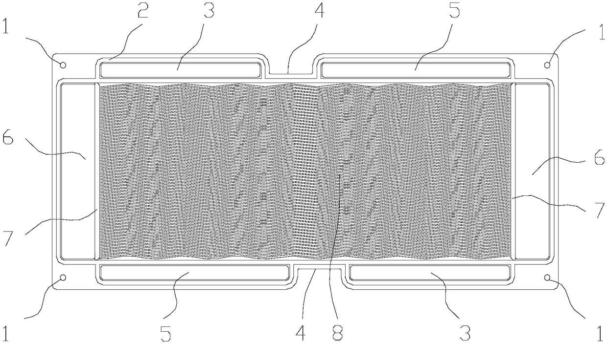
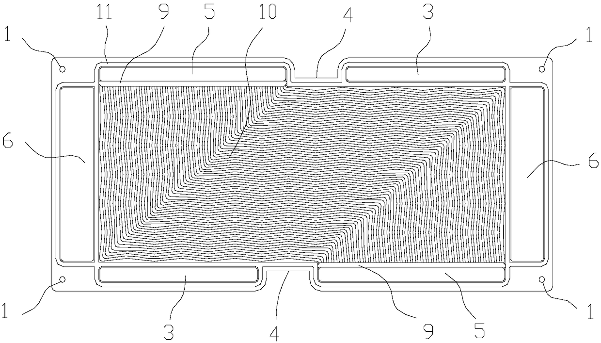
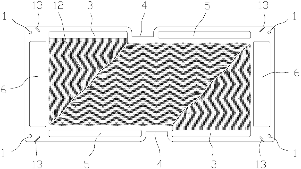
[0080] A fuel cell stack flow field plate supporting high current density discharge, including a cathode flow field plate and an anode flow field plate oppositely connected on the back, and its structures are as follows figure 1 and figure 2 As shown, the fronts of the cathode flow field plate and the anode flow field plate are respectively processed with corrugated air flow field channels 8 and hydrogen flow field channels 10. This water corrugated design is conducive to increasing the turbulent flow of air and hydrogen. , to achieve the effect of promoting its transmission in the direction perpendicular to the gas diffusion layer. A cooling water flow field channel 12 is processed between the back of the cathode flow field plate and the anode flow field plate, such as image 3 As shown, in this embodiment, the backside of the anode flow field plate is processed, and the cathode flow field plate and the anode flow field plate are combined by laser welding to form the follow...

Embodiment 2

[0089] The difference from Embodiment 1 is that in this embodiment, the metal cathode flow field plate and the anode flow field plate are combined using sealant instead of welding. Such as Figure 4 As shown, the back side of the anode flow field plate, that is, the side of the water flow field, around the cooling water flow field channel 12, increases the preformed glue line that can be used to install or use a high-viscosity sealant to form a seal in situ. sealing groove. If pre-formed glue lines are installed, the glue lines must be completely flattened after the stack assembly is pressed to ensure good electrical contact; if a high-viscosity sealant is used to form the seal in situ, it needs to be sealed before the sealant cures. Use corresponding clamps to press the cathode and anode flow field plates together until the sealant is completely cured before releasing. The advantage of adopting this combination method is to avoid thermal swelling, deformation, twisting or w...

Embodiment 3

[0094] The difference from the previous two embodiments is that in this embodiment, the material of the flow field plate is changed to graphite, and the rest are the same as in Example 2. In this embodiment, a sealant is used to combine the cathode flow field plate and the anode flow plate. field board. Compared with metal plates, graphite plates have excellent corrosion resistance, but slightly poorer electrical conductivity than metal plates.

[0095] The design of the graphite flow field plate is exactly the same as that of the second embodiment, and will not be repeated here.

[0096] Likewise, the present embodiment adopts active area 340cm 2 The flow field plate and MEA are used to assemble a 15-section small electric stack. Figure 12 For its polarization curve, the test conditions are as follows: the air / hydrogen stoichiometric ratio is 2.5 / 1.4; the air / hydrogen inlet pressure is 120kPa / 125kPa; the air / hydrogen inlet humidity is controlled at 80%RH. It can be seen f...


PUM


Abstract

The invention relates to a fuel cell stack flow field plate capable of supporting high-current density discharging. The fuel cell stack flow field plate comprises a negative flow field plate and a negative flow field plate, wherein back surfaces of the negative flow field plate and the negative flow field plate are oppositely connected, a water ripple-type air flow field passage and a water ripple-type hydrogen flow field passage are respectively processed in front surfaces of the negative flow field plate and the positive flow field plate, a cooling water flow field passage is processed between the back surfaces of the negative flow field plate and the positive flow field plate, a pair of common air passages, a pair of common hydrogen passages and a pair of common water passages are arranged on the negative flow field plate and the positive flow field plate and communicate with each other, and an air inlet/outlet, a hydrogen inlet/outlet and a cooling water inlet/outlet of an inlet port and an outlet port which are connected with the air flow field passage, the hydrogen flow field passage and the cooling water flow field passage are respectively formed. The flow field plate employs more optical runner design, more excellent material formula and more optimal assembly mode, so that the purposes of large-current discharging, temperature uniformity, low-temperature rapid startingsupporting, loading and rapid response to load change are achieved.

Description

technical field [0001] The invention relates to the field of fuel cells, in particular to a fuel cell electric stack flow field plate supporting high current density discharge. Background technique [0002] Under the background of serious air pollution and high oil prices in our country, the development of new energy vehicles has been put on the important agenda from the central to local governments. Different from pure electric vehicles using lithium-ion batteries that have already started commercialization, fuel cell vehicles have the outstanding advantages of fast refueling, high energy density, and long battery life. Vehicle fuel cells generally use proton exchange membrane fuel cells (PEMFC), which use air or pure oxygen as the oxidant, and hydrogen-rich reformed gas from hydrocarbon fuel cells such as pure hydrogen or methane as fuel. Due to the wide range of sources of hydrogen, the fuel cell, an electrochemical conversion device, has high energy conversion efficienc...

Claims


Application Information

Patent Timeline
IPC IPC(8): H01M8/0254H01M8/026H01M8/0263
CPCH01M8/0254H01M8/026H01M8/0263Y02E60/50
Inventor 杨代军李冰张存满
Owner TONGJI UNIV
Why Eureka
Try Eureka