
Fluidized-bed pyrolysis device for preparing biomass gas with high calorific value

A technology of biomass gas and fluidized bed, which is applied in the direction of gasification device feeding tools, manufacture of combustible gas, granular/powdered fuel gasification, etc. It can solve the problems of no practical case, high operating cost, and poor economy. Achieve the effects of avoiding the separation process of nitrogen and gas, improving heat and mass transfer efficiency, and realizing multi-level utilization of energy

Pending Publication Date: 2018-06-22
广东国能中林实业有限公司
View PDF6 Cites 0 Cited by
  • Summary
  • Abstract
  • Description
  • Claims
  • Application Information

AI Technical Summary

Problems solved by technology

When oxygen-enriched or pure oxygen is used as the gasification agent, the reaction temperature is high, the reaction speed is fast, the tar content is low, and the calorific value is high (up to 2500kCal / Nm3), but the cost of oxygen production is high and the economy is poor
When water vapor is used as the gasification agent, the gas quality is good, the hydrogen content is high, and the gas with a medium calorific value (4200kCal / Nm3) is produced, or when air and water vapor are used together as the gasification agent, the calorific value can also reach 2500kCal / Nm3 or more, but the system needs to be equipped with steam generators and superheating equipment, as well as external heat supply sources, poor system independence, complicated technology, and high operating costs
Hydrogen gasification is a process in which hydrogen reacts with carbon and water to generate a large amount of methane. The reaction conditions are harsh, and it needs to be carried out under the conditions of high temperature and high pressure and a hydrogen source. It can produce high calorific value gas with a calorific value of about 5800kCal / Nm3. There are basically no actual cases

Method used


Image

  • Fluidized-bed pyrolysis device for preparing biomass gas with high calorific value

Examples


Embodiment

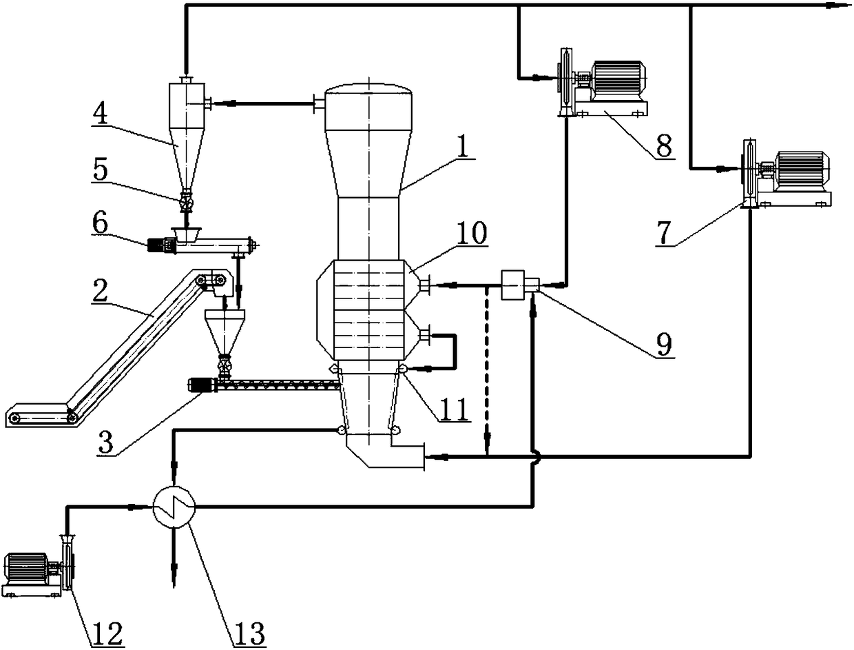
[0026] Please refer to figure 1 , a fluidized bed pyrolysis device for preparing high calorific value biomass gas, comprising a fluidized bed 1, a cyclone separator 4, a heat exchanger 10 and a feeder 3, and the feeder 3 is used for crushing and drying biomass The material material is sent to the fluidized bed 1, the inlet of the cyclone separator 4 is connected with the top of the fluidized bed 1, and the heat exchanger 10 is arranged in the dense phase section in the fluidized bed, and the heat exchanger 10 is The biomass material provides the heat required for pyrolysis, and also includes a booster fan 8 and a biomass gas burner 9. The exhaust port of the cyclone separator 4 is connected with the inlet of the booster fan 8, and the outlet of the booster fan 8 The gas port is connected with the air inlet of the burner 9 , and the hot flue gas outlet of the burner 9 is connected with the heat medium inlet of the heat exchanger 100 . Wherein, the heat exchanger 10 is a silico...


PUM


Abstract

The invention discloses a fluidized-bed pyrolysis device for preparing biomass gas with high calorific value. The fluidized-bed pyrolysis device comprises a fluidized bed, a cyclone separator, a heatexchanger and a feeder, wherein the feeder is used for conveying crushed and dried biomass materials into the fluidized bed; an inlet of the cyclone separator is communicated with the top part of thefluidized bed; the heat exchanger is arranged at a dense-phase section in the fluidized bed, and provides heat needed by pyrolysis for the biomass materials by heat exchange. The fluidized-bed pyrolysis device also comprises a booster fan and a biomass-gas burner; an exhausting port of the cyclone separator is connected with a gas inlet of the booster fan; a gas outlet of the booster fan is connected with a gas inlet of the burner; a hot-smoke outlet of the burner is connected with a hot-medium inlet of the heat exchanger. Compared with the prior art, the fluidized-bed pyrolysis device disclosed by the invention has the advantages that the heat needed by thermal cracking in a furnace is met by self-produced gas; compared with the pyrolysis mode utilizing external fuel and electric energy,the fluidized-bed pyrolysis device has the advantage that the operation cost is reduced.

Description

technical field [0001] The invention relates to a fluidized bed pyrolysis device for preparing high calorific value biomass gas. Background technique [0002] Biomass solid waste is rich in resources, vigorously developing the resource utilization of biomass solid waste will help to improve my country's energy structure dominated by fossil fuels, which can not only reduce the emission of sulfide and nitrogen oxides, but also relieve the effect. Biomass pyrolysis gasification technology realizes the transformation of low-grade biomass into high-quality gas, which can replace fossil energy such as coal and petroleum in many fields. Biomass gasification is a more efficient biomass energy utilization technology. The basic principle is that biomass is insufficiently oxidized with gasification agents (such as air, oxygen or water vapor) at relatively high temperatures (700-900°C). The reaction produces a flammable gas mainly composed of carbon monoxide, hydrogen and methane. Bio...

Claims


Application Information

Patent Timeline
Patent Type & Authority Applications(China)
IPC IPC(8): C10J3/56C10J3/60C10J3/72
CPCC10J3/56C10J3/60C10J3/72C10J2300/1807C10J2300/1823C10J2300/1876C10J2300/1207C10J2300/1223C10J2300/0909C10J2200/15C10J2300/0953C10J2300/0916
Inventor 林进猛姜辉胡洪
Owner 广东国能中林实业有限公司
Learn More