Micro heating disc and manufacturing method thereof

A manufacturing method and micro-thermal technology, applied in the field of microelectronic systems, can solve the problems of limiting the integration of single-chip systems, increasing the difficulty of chip bonding, limiting product miniaturization, etc., to simplify the through hole etching process, small temperature gradient, The effect of stress relief

Active Publication Date: 2018-07-10
武汉微纳传感技术有限公司
View PDF6 Cites 4 Cited by
  • Summary
  • Abstract
  • Description
  • Claims
  • Application Information

AI Technical Summary

Problems solved by technology

When the micro-hot plate (that is, the micro-hot plate chip) is packaged and working, due to the effect of gas thermal expansion and contraction and atmospheric pressure fluctuations, the temperature isolation cavity needs to be connected to the ambient air to achieve pressure balance on both sides of the film. The product size continues to shrink, and the temperature isolation cavity is getting smaller and smaller, which increases the difficulty of chip bonding and makes it difficult to form gas conduction channels on ordinary packaging substrates
The traditional solution is: the microchip needs to adopt a special packaging structure, which increases the complexity of the packaging, and the airtight suspension film structure can only use the backside etching process, which limits the further miniaturization of the product and limits the integration of the single chip system

Method used


Image

  • Micro heating disc and manufacturing method thereof
  • Micro heating disc and manufacturing method thereof
  • Micro heating disc and manufacturing method thereof

Examples


Embodiment 1

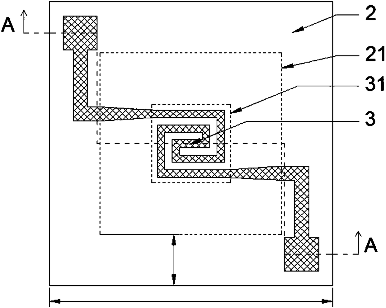
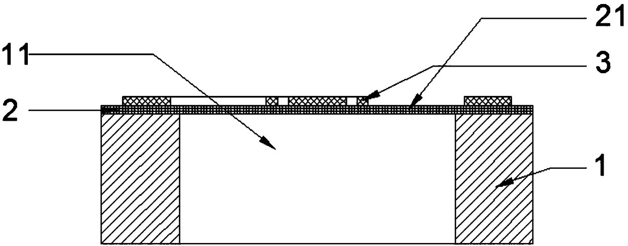
[0043] A micro hot plate, such as image 3 and Figure 4As shown, it includes: a substrate 1, an insulating support layer 2 and a resistance heating layer 3 stacked sequentially from bottom to top, a temperature isolation cavity 11 is arranged in the middle of the substrate 1, and the insulation support layer on the upper part of the temperature isolation cavity 11 is The temperature isolation suspension film 21, the resistance heating layer 3 is located on the insulating support layer 2, the heating area 31 of the resistance heating layer 3 is located in the middle part of the temperature isolation suspension film 21, and the substrate at the edge of the temperature isolation cavity 11 is provided with a The isolation cavity 11 is connected to the integrated deformation isolation cavity 12, and the insulating support layer on the upper part of the deformation isolation cavity 12 is a deformation isolation suspension film 22, and the deformation isolation suspension film 22 is...

Embodiment 2

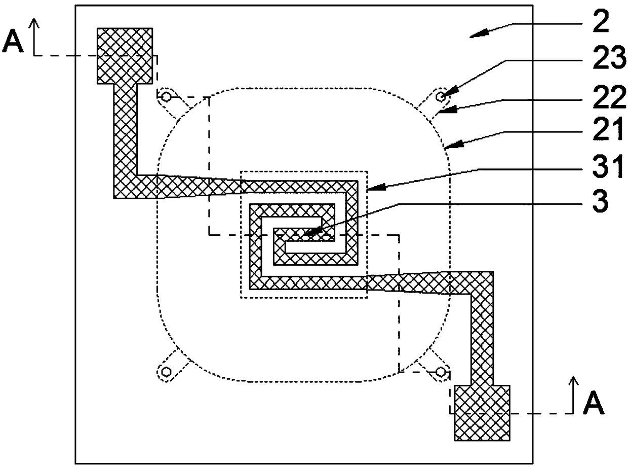
[0059] A micro hot plate, such as Figure 5 and Image 6 As shown, it includes: a substrate 1, an insulating support layer 2, and a resistance heating layer 3. The insulating support layer 2 is arranged on the substrate 1, the resistance heating layer 3 is arranged on the insulating support layer 2, and the substrate 1 is provided with temperature isolation. Cavity 11, the insulating support layer 2 on the top of the temperature isolation cavity 11 is a temperature isolation suspension film 21, a deformation isolation cavity 12 is arranged on the edge of the temperature isolation cavity 11, and the insulation support layer 2 on the top of the deformation isolation cavity 12 In order to deform the isolation suspension membrane 22, two semi-annular through holes 23 are arranged on the deformation isolation suspension membrane 22.

[0060] Wherein, the material of the substrate 1 is single crystal silicon, the material of the insulating support layer 2 is silicon nitride, and th...


PUM


Abstract

The invention relates to a micro heating disc and manufacturing method thereof. The micro heating disc comprises a substrate, an insulated support layer and a resistance heating layer which are stacked from bottom to top successively, the middle of the substrate is provided with a temperature isolated cavity, the insulated support layer in the upper portion of the temperature isolated cavity includes a temperature isolated suspension film, the substrate in the edge of the temperature isolated cavity is provided with a deformation isolated cavity communicated and integrated with the temperatureisolated cavity, a suspension film in the upper portion of the deformation isolated cavity is a deformation suspension film, and the deformation isolated suspension film is provided with through holes through which the air pressure of the temperature isolated cavity of the micro heating disk is balanced with that of the external environment. The structure of deformation isolated cavity is used, the through holes are formed in the deformation isolated suspension film to balance pressures at the two sides of the suspension film and eliminate pressure caused by temperature gradients in the through holes, deformation of the temperature isolated suspension film is inhibited from being conducted to the deformation isolated suspension film, the micro heating disc can bear a higher work temperature, the packaging technology is simple, integration of a single-chip system can be carried out, and a product can be more micro.

Description

technical field [0001] The invention relates to the technical field of microelectronic systems, in particular to a micro hot plate and a manufacturing method thereof. Background technique [0002] Micro hot plate devices are widely used in products that require local high temperature, including high temperature chemical sensors, micro chemical reactors, infrared light sources, flow sensors, etc. [0003] The micro-thermal plate achieves small size and low power consumption through temperature isolation technology. The temperature isolation structure of the micro-thermal disk can be a MEMS (microelectronic system) process suspension film or beam, or a high-porosity material with low thermal conductivity and a bulk material with low thermal conductivity. When the micro-hot plate works at high temperature, considering the influence of structural deformation caused by thermal stress, a closed suspension film structure is often used. In order to obtain a closed suspension film ...

Claims


Application Information

Patent Timeline
Patent Type & Authority Applications(China)
IPC IPC(8): H05B3/26H05B3/02H05B3/10B81C1/00B81B7/02
CPCB81B7/02B81C1/0015B81C1/00349B81C1/00523H05B3/02H05B3/10H05B3/26H05B2203/017
Inventor 雷鸣饶吉磊贺方杰
Owner 武汉微纳传感技术有限公司
Why Eureka
Try Eureka