Curved magnetron sputtering cathode, closed magnetic field coating magnetron sputtering equipment and application methods thereof

A magnetron sputtering, curved surface technology, applied in closed magnetic field coating equipment, curved magnetron sputtering cathode, optical film, preparation of decorative coating, diamond-like coating field, can solve the problem of low production efficiency and effective deposition area Small, low atomic energy and other problems, to achieve the effect of improving uniformity and quality, increasing sputtering rate, and enhancing ionization rate

Active Publication Date: 2018-08-14
WENZHOU POLYTECHNIC
View PDF5 Cites 7 Cited by
  • Summary
  • Abstract
  • Description
  • Claims
  • Application Information

AI Technical Summary

Problems solved by technology

However, there are still many problems in the preparation process of diamond-like coatings
[0006] The existing DLC ​​deposition technologies are mainly physical vapor deposition (PVD) and chemical vapor deposition (CVD). PVD mainly includes ion beam deposition (IBD), magnetron sputtering, multi-arc ion plating, pulsed laser deposition, etc. CVD includes thermal Silk chemical vapor deposition and plasma chemically enhanced vapor deposition (PECVD) have some problems: ion beam deposition has low sputtering rate and low deposition rate due to graphite sputtering; magnetron sputtering deposition has low sputtering rate on the one hand and low On the one hand, low atomic energy leads to loose structure and low hardness; a large number of carbon particles will be produced during multi-arc ion plating deposition; pulsed laser deposition has high energy consumption, poor coating uniformity, and small effective deposition area; hot wire vapor deposition technology has high deposition temperature, The range of matrix materials is greatly limited; although PECVD effectively reduces the reaction temperature, the deposition efficiency is low during

Method used


Image

  • Curved magnetron sputtering cathode, closed magnetic field coating magnetron sputtering equipment and application methods thereof
  • Curved magnetron sputtering cathode, closed magnetic field coating magnetron sputtering equipment and application methods thereof
  • Curved magnetron sputtering cathode, closed magnetic field coating magnetron sputtering equipment and application methods thereof

Examples


Embodiment Construction

[0066] In order to make the object, technical solution and advantages of the present invention clearer, the present invention will be further described in detail below in conjunction with the accompanying drawings.

[0067]The terms of direction and position mentioned in the present invention, such as "up", "down", "front", "back", "left", "right", "inside", "outside", "top", "bottom" ", "side", etc., are only referring to the direction or position of the drawings. Therefore, the terms used in direction and position are used to explain and understand the present invention, but not to limit the protection scope of the present invention.

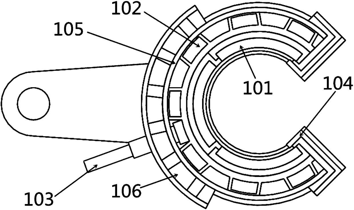
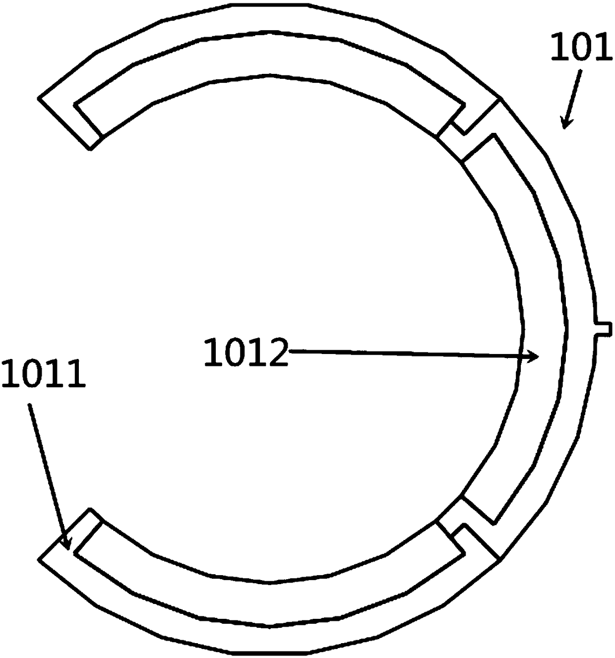
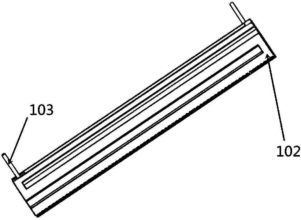
[0068] Such as Figure 1 to Figure 5 As shown, in the embodiment of the present invention, in order to facilitate drawing, in the diamond-like coating curved surface magnetron sputtering cathode, the water-cooled back-shaped pipeline is welded on the cooling steel pipe, and the target material is assembled in three sets of tiles. In practical...


PUM


Abstract

The invention discloses a curved magnetron sputtering cathode, closed magnetic field coating magnetron sputtering equipment and application methods thereof. The curved magnetron sputtering cathode comprises a curved target material, a water jacket, an electrode, an insulating bush, a shielding component, a magnetic boot, a magnetic boot rotating component and a supporting and fixing mechanism, wherein the insulating bush performs potential insulation on a cathode component; the shielding component is a suspended potential component in a discharge process; and the magnetic boot rotating component can realize sliding of the magnetic boot. The utilization ratio of the magnetic material is improved; the curved target material is formed by splicing a plurality of metal-based tiles, of which thesurfaces can be bonded with nonmetals, and is fixed on the water jacket which is formed by welding the surface of a stainless steel tube with a water-cooled tube; the electrode is connected with a negative voltage to perform magnetron sputtering glow discharge; and limited by the shape of the cathode, electrons in glow discharge are gathered to produce a hollow cathode effect, so that not only the sputtering rate but also the particle ionization rate is improved. The curved magnetron sputtering cathode can perform magnetron sputtering in a high-vacuum state to generate big-beam high-ionization-rate particles so as to obtain a high-quality coating.

Description

technical field [0001] The invention belongs to the technical field of magnetron sputtering coating production equipment, and specifically refers to a curved surface magnetron sputtering cathode, closed magnetic field coating equipment and a preparation method applied to diamond-like coatings, optical films and decorative coatings. Background technique [0002] Magnetron sputtering technology is widely used in hardware decoration, optical glass coating, thin-film solar energy, nano-functional thin film, hard coating and other fields. It is the most widely used in physical vapor deposition (PVD) technology. Energetic particles bombard the surface of the target under the action of an electric field, and the atoms of the target obtain energy after cascading collision energy transfer, overflowing the surface of the target and depositing on the surface of the substrate to form a film or coating. During the sputtering process, the main function of the electrons in the plasma is to...

Claims


Application Information

Patent Timeline
IPC IPC(8): C23C14/35C23C14/06C23C14/18C23C14/10C23C14/08C23C14/14C23C14/02
CPCC23C14/0036C23C14/0084C23C14/025C23C14/0611C23C14/0635C23C14/0641C23C14/0652C23C14/0664C23C14/083C23C14/10C23C14/185C23C14/35C23C14/352
Inventor 郎文昌
Owner WENZHOU POLYTECHNIC
Why Eureka
Try Eureka