
Method for welding combustor liner and tile pads of aeroengine

A technology of aero-engines and welding methods, applied in welding equipment, arc welding equipment, manufacturing tools, etc., can solve the problems of increased production cost and cycle, large amount of metal cutting, low material utilization rate, etc., to increase production cost and cycle problems, large amount of metal removal, and low material utilization

Active Publication Date: 2018-09-07
广汉天空动力机械有限责任公司
View PDF7 Cites 4 Cited by
  • Summary
  • Abstract
  • Description
  • Claims
  • Application Information

AI Technical Summary

Problems solved by technology

[0014] The purpose of the present invention is to solve the problem that the existing argon arc welding with large heat input after welding has large deformation or even the welding penetration of floating tiles, or the phenomenon of incomplete penetration may occur in the central area where the studs and floating tiles are connected. This in turn affects the welding strength. The studs are mainly positioned by workers after scribing. The errors in scribing and dotting positioning during manual operation are large, which leads to low stud welding positioning accuracy. The overall machining method has a large amount of metal cutting, which not only uses Low rate, long processing cycle, and in the process of machining and cutting, high temperature cutting thermal deformation is prone to occur, and a stress relief heat treatment process is required after processing, which further increases the production cost and cycle problems

Method used


Image

  • Method for welding combustor liner and tile pads of aeroengine
  • Method for welding combustor liner and tile pads of aeroengine
  • Method for welding combustor liner and tile pads of aeroengine

Examples


Embodiment 1

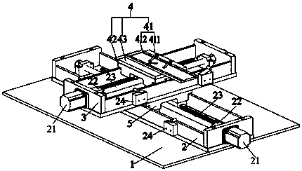
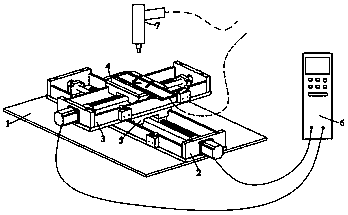
[0055] as attached figure 1 , attached figure 2 , attached image 3 , attached Figure 4 , attached Figure 5 A kind of aeroengine flame tube tile welding method shown in this embodiment comprises fixture base 1, X slide rail 2, motor 21, shaft coupling 22, screw mandrel 23, limiter 24, Y slide rail 3, clamping device 4 , clamping part 41, piano key press 411, metal backing plate 412, slider 1 42, rubber pad 43, slider 2 5, controller 6, stud welding machine 7, floating tile 8, stud 9, arc The basic principle of stud welding is to ignite the arc between the stud to be welded and the workpiece. When the stud and the workpiece are heated to a suitable temperature, under the action of external force, the stud is sent into the welding pool on the workpiece to form a welded joint. The welding process is short time, high current and small penetration during stud welding, so it can be welded to very thin plates. For the plate thickness of short-cycle drawn arc stud welding, it ...


PUM


Abstract

The invention relates to the technical field of aeroengines, in particular to a method for welding a combustor liner and tile pads of an aeroengine. The method for welding the combustor liner and thetile pads of the aeroengine comprises floating tile blocks and studs, and the floating tile blocks and the studs use forging pieces as raw materials, and the welding technological steps of the floating tile blocks and the studs are as follows: (1) machining; (2) surface treatment; (3) clamping; (4) stud welding; (5) gripping and repairing; and (6) inspection. By adopting the method disclosed by the invention, the studs are welded to the floating tile blocks by adopting a argon arc welding way, and the verticality deviation of the studs is larger; meanwhile, the phenomenon of incomplete fusionin a central area on which the studs are connected with the floating tile blocks possibly occurs so as to affect the welding strength and low welding and positioning precision of the studs; by adopting an overall machining way, the metal cutting quantity is large, so that a material utilization ratio of the materials is low, and a machining period is long; and moreover, in a machining and cuttingprocess, high-temperature cutting heat deformation easily occurs, and a destressing heat treatment procedures are required after machining, so that the problems of the production cost and the periodsare further increased.

Description

technical field [0001] The invention relates to the technical field of aero-engines, in particular to a method for welding blocks of an aero-engine flame cylinder. Background technique [0002] The combustion chamber of an aero-engine is one of the important parts of the engine, and it is the part that bears the greatest heat load. The reliability, economy and life of the engine depend to a large extent on the reliability and effectiveness of the combustion chamber. The working conditions of the combustion chamber are very harsh, and its parts work under high temperature and high load, and bear multiple effects such as static load, dynamic load, thermal stress and thermal corrosion. The floating wall tile is one of the very important parts in the flame tube of the high thrust-to-weight ratio aero-engine combustor. It is generally assembled on the outer side of the inner wall of the flame tube and the inner side of the outer wall. A cooling airflow channel is formed between ...

Claims


Application Information

Patent Timeline
Patent Type & Authority Applications(China)
IPC IPC(8): B23K9/20B23P15/00
CPCB23K9/20B23P15/00
Inventor 吴超杰曹文明张周黄林刘睿刘桂松
Owner 广汉天空动力机械有限责任公司
Learn More