Deep purification method and system of polycrystalline silicon reduction exhaust gas

A polysilicon and tail gas technology, applied in chemical instruments and methods, separation methods, liquefaction, etc., can solve the problems of large cooling capacity consumption, increased absorption tower load, large fluctuation of hydrogen quality, etc., to reduce costs and energy consumption, reduce Delay time, the effect of reducing cooling energy consumption

Active Publication Date: 2018-09-14
XINTE ENERGY
View PDF6 Cites 5 Cited by
  • Summary
  • Abstract
  • Description
  • Claims
  • Application Information

AI Technical Summary

Problems solved by technology

[0009] Combining the analysis of the consumption degree of cooling capacity and the influencing factors of the recovered hydrogen quality, it can be seen that in the process of low-pressure condensation, Freon is usually used to deeply condense the reduction tail gas, which requires a large amount of cooling capacity and directly enters the absorption tower. There is more hydrogen chloride gas in the mixed gas, which increases the load of the absorption tower;
[0010] Moreover, since the absorption tower needs a low-temperature and high-pressure environment to remove a large amount of hydrogen chloride gas in the mixed gas, but the temperature in the northern quarter changes greatly, making the temperature in the absorption tower unstable, resulting in fluctuations in the quality of hydrogen output from the top of the tower Larger, which further leads to an increase in the delay time of the adsorption column;
[0011] In addition, carbon molecules will be entrained in the pure hydrogen gas output from the top of the tower after being adsorbed by activated carbon. When polysilicon is produced using this hydrogen gas entrained with carbon molecules, it will affect the carbon concentration of polysilicon, so that the quality of polysilicon cannot be effectively improved, resulting in production The polysilicon cannot meet the corresponding requirements of electronic grade polysilicon (hydrogen chloride content <50ppm, carbon content <3ppm)

Method used


Image

  • Deep purification method and system of polycrystalline silicon reduction exhaust gas
  • Deep purification method and system of polycrystalline silicon reduction exhaust gas
  • Deep purification method and system of polycrystalline silicon reduction exhaust gas

Examples


Embodiment 1

[0041] This embodiment provides a method for deep purification of polysilicon reduction tail gas. The reduction tail gas comes from the upstream polysilicon production process, and specifically includes a mixed gas of hydrogen, hydrogen chloride, chlorosilane and a small amount of impurities, wherein the chlorosilane includes silicon tetrachloride, trichloro A mixed gas of hydrogen silicon and dichlorodihydrogen silicon, the impurities include phosphorus, boron, iron, etc., and the content of the impurities in the reducing tail gas is 2ppm-5ppm.

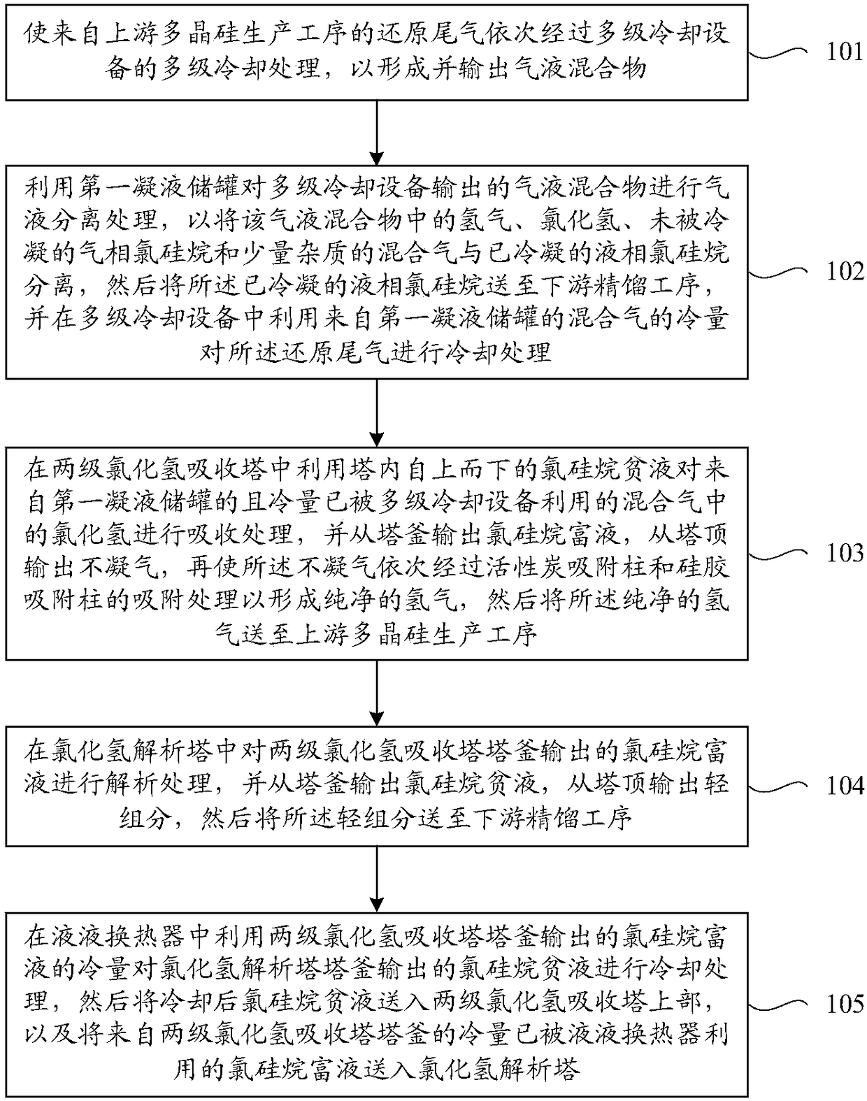
[0042] Such as figure 1 As shown, the purification method includes the following steps S101 to S105.

[0043] S101. Make the reduction tail gas from the upstream polysilicon production process sequentially undergo multi-stage cooling treatment of multi-stage cooling equipment to form and output a gas-liquid mixture, which includes hydrogen, hydrogen chloride, uncondensed gas phase chlorosilane and a small amount of impurities. Mixed...

Embodiment 2

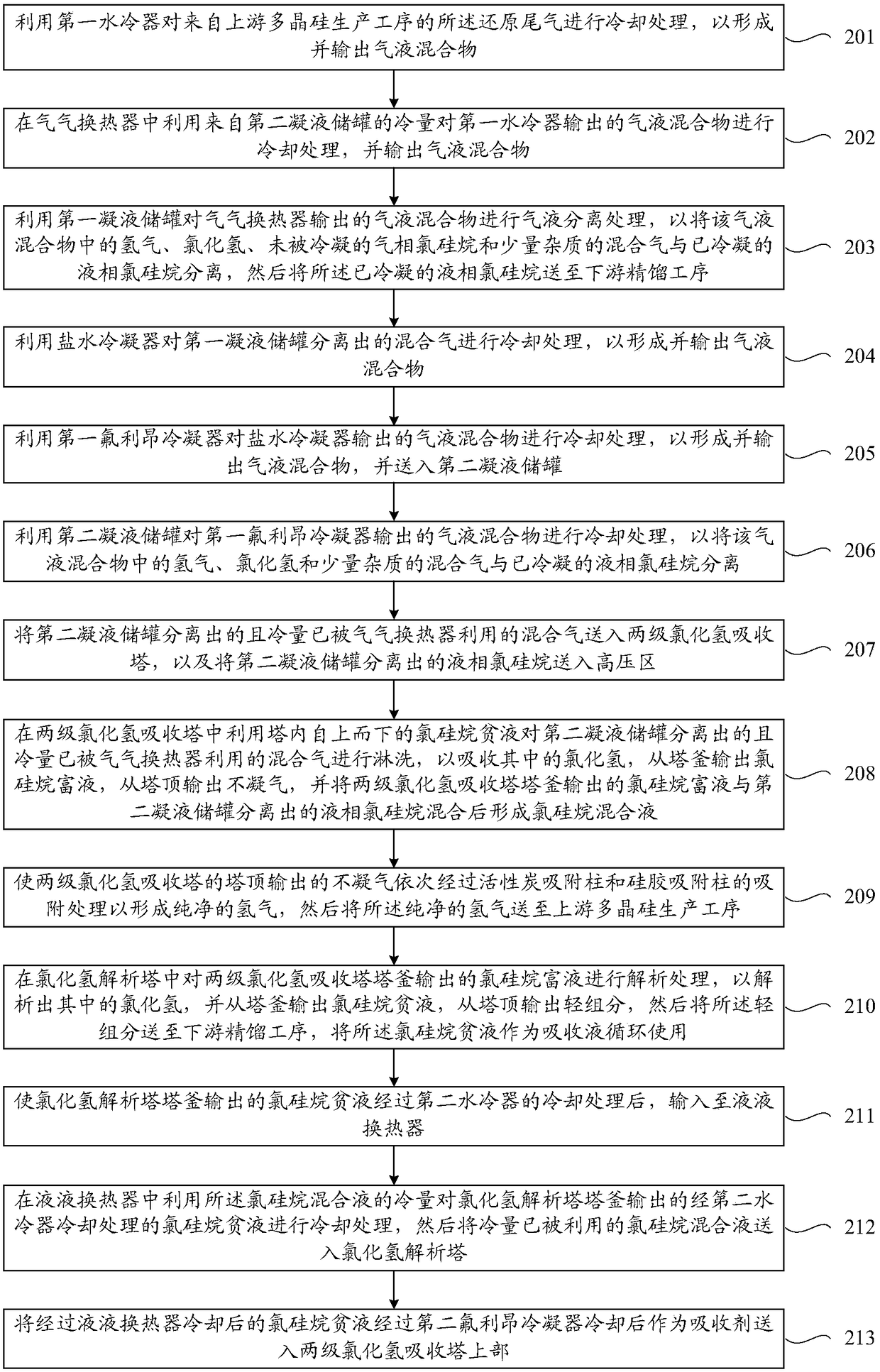
[0058] This embodiment provides a method for deep purification of polysilicon reduction tail gas. Such as figure 2 As shown, the purification method includes the following steps S201 to S213.

[0059] It should be noted that the first water cooler, air-gas heat exchanger, first condensate storage tank, first delivery pump, brine condenser, first Freon condenser, and second condensate storage tank involved in the following steps and the second delivery pump are located in the low-pressure area, the pressure range is 0.3-0.5MPa, preferably 0.45MPa. The compressor, two-stage hydrogen chloride absorption tower, liquid-liquid heat exchanger, hydrogen chloride desorption tower, second water cooler, circulation pump, second Freon condenser, deep cooler, activated carbon adsorption column and silica gel adsorption column are all located in the high-pressure area. Among them, the pressure range adopted by the two-stage hydrogen chloride absorption tower is 1.4~1.7MPa, preferably 1.6...

Embodiment 3

[0111] This embodiment provides a polysilicon reduction tail gas deep purification system. The reduction tail gas comes from the upstream polysilicon production process, and specifically includes a mixture of hydrogen, hydrogen chloride, chlorosilane and a small amount of impurities, wherein the chlorosilane includes silicon tetrachloride, trichloro A mixed gas of hydrogen silicon and dichlorodihydrogen silicon, the impurities include phosphorus, boron, iron, etc., and the content of the impurities in the reducing tail gas is 2ppm-5ppm.

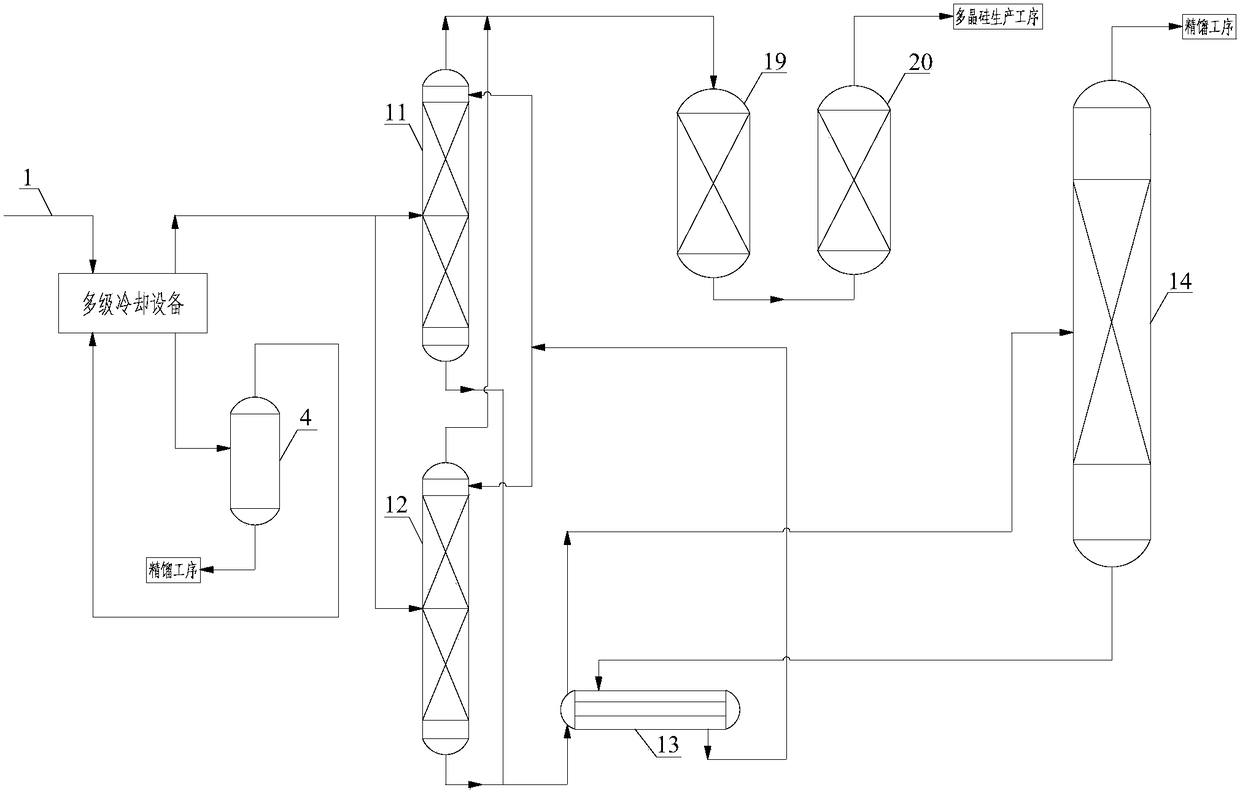
[0112] Such as image 3 and 4 As shown, the purification system includes multi-stage cooling equipment, the first condensate storage tank 4, two-stage hydrogen chloride absorption towers 11 and 12, activated carbon adsorption column 19, silica gel adsorption column 20, hydrogen chloride desorption tower 14 and liquid-liquid heat exchanger 13.

[0113] The multi-stage cooling equipment is used to receive the reduction tail gas 1 from the ups...


PUM


Abstract

The invention provides a deep purification method of polycrystalline silicon reduction exhaust gas, comprising: performing multiple stages of cooling treatment successively on reduction exhaust gas soas to discharge gas-liquid mixture; performing gas-liquid separation on the gas-liquid mixture, using cold capacity of separated mixed gas to cool the reduction exhaust gas; using chlorosilane barrenliquor that runs from top to bottom inside a two-stage hydrogen chloride absorbing column to absorb, in the column, hydrogen chloride in the mixed gas with the cold capacity already utilized; stripping, in a hydrogen chloride stripper, chlorosilane rich liquor discharged from the bottom of the hydrogen chloride absorbing column, and discharging fluorosilicon barren liquor from the bottom and light components from the top; using the cold capacity of chlorosilane rich liquor, discharged from the bottom of the two-stage hydrogen chloride absorbing column, to cool the chlorosilane barren liquor discharged from the bottom of the hydrogen chloride stripper. Correspondingly, a deep purification system is provided. The deep purification method and system have the advantages that the quality of recycled hydrogen meets the corresponding requirements of electronic polycrystalline silicone, extra cold consumption is decreased, and load of the absorbing column is relieved.

Description

technical field [0001] The invention relates to the technical field of polysilicon production, in particular to a polysilicon reduction tail gas deep purification method and a polysilicon reduction tail gas deep purification system. Background technique [0002] In the current era of increasing shortage of fossil energy, the rise of new energy has become an inevitable trend. As a key raw material for integrated circuits and photovoltaic power generation, polysilicon is the basic material for the country's new energy development. However, as the basic material of new energy, the production of polysilicon is a production process with high energy consumption, and the quality requirements for polysilicon are becoming higher and higher. With the formulation of polysilicon grading standards, the quality requirements of polysilicon pose greater challenges. [0003] At present, polysilicon is mainly produced by the improved Siemens method (that is, the reduction method of trichlor...

Claims


Application Information

Patent Timeline
Patent Type & Authority Applications(China)
IPC IPC(8): F25J3/08B01D53/14B01D53/04
CPCB01D53/04B01D53/1406B01D53/1431B01D53/1456B01D2253/102B01D2253/106B01D2257/2045B01D2258/02F25J3/08F25J2205/40F25J2205/60F25J2215/10
Inventor 蒋鹏陈国辉陈喜清杜新王玉丽颉刚刚刘想林马金杉
Owner XINTE ENERGY
Why Eureka
Try Eureka