A high-precision chaotic optical time domain reflectometer

A technology of time domain reflectometer and chaotic light, which is applied in the direction of optical fiber transmission, digital transmission system, electromagnetic transceiver, etc., can solve the problems of limited bandwidth, reduced dynamic range, low resolution, etc., to overcome the limitation of bandwidth and noise tolerance The effect of large degree and strong anti-interference ability

Active Publication Date: 2021-01-08
TAIYUAN UNIV OF TECH
View PDF6 Cites 0 Cited by
  • Summary
  • Abstract
  • Description
  • Claims
  • Application Information

AI Technical Summary

Problems solved by technology

For traditional OTDRs that use pulsed lasers as light sources, the problem is that the resolution is low, and its resolution is limited by the width of the optical pulse, and the peak power of the OTDR transmitter is limited by the laser. The improvement of the dynamic range is mainly achieved by increasing the With the realization of optical pulse energy, increasing the dynamic range will reduce the resolution of OTDR, and increasing the resolution will reduce the dynamic range. This is the contradiction that traditional pulsed OTDR cannot solve.
However, at present, the chaotic light source in COTDR is mainly composed of a semiconductor laser and an external cavity feedback device. Its structure is simple, but the chaotic light relaxation oscillation generated is obvious, which limits its bandwidth.
In order to further increase the bandwidth of chaotic light sources, more complex structures must be adopted, such as optical injection method to generate chaos (Optics Letters, 2009, 34 (8): 1144-1146), optical fiber oscillation ring to generate chaos (Applied Physics Letters, 2013 , 102(3):031112), which will result in complex structure and increased cost
At the same time, considering the cost of photodetectors (PDs) in COTDR, the bandwidth of COTDR detectors in commercial use is much smaller than the bandwidth of chaotic light sources, resulting in low bandwidth utilization of chaotic light sources
Limited by the cost of PD, the highest resolution of COTDR reported so far is 2cm@1GHz PD

Method used


Image

  • A high-precision chaotic optical time domain reflectometer
  • A high-precision chaotic optical time domain reflectometer
  • A high-precision chaotic optical time domain reflectometer

Examples


Embodiment Construction

[0019] The present invention will be further described below in conjunction with specific examples.

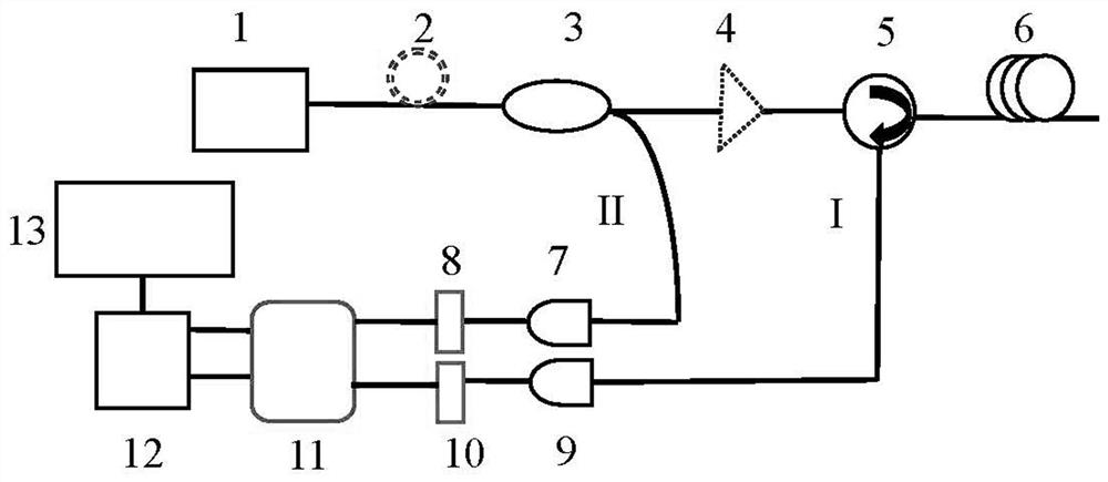
[0020] A high-precision chaotic optical time domain reflectometer, such as figure 1 As shown, it includes a chaotic light emitting device 1, a fiber coupler 3, a photodetector, a cross-correlation processing device 12, a display device 13, two n-bit ADCs and an effective bit information processing system 11; the chaotic light emitted by the chaotic light emitting device 1 The optical signal is divided into probe light I and reference light II through the fiber coupler 3; the probe light I is transmitted to the optical fiber line 6 to be tested through the optical circulator 5, and the photodetector I9 is ​​used to receive the reflected light from the optical fiber line 6 to be tested. Probe light I is quantified by n-bit ADCⅠ10, and each sampling point is quantized into n binary bits and input into effective bit information processing system 11; reference light II is received...


PUM


Abstract

The invention discloses a high-precision chaos optical time domain reflectometer. According to a principle, a chaos optical signal transmitted by a chaos optical transmitting device is divided into detection light I and reference light II through an optical fiber coupler I; the detection light I is transmitted to a to-be-detected optical fiber circuit through an optical circulator; the detection light transmitted back from the to-be-detected optical fiber circuit is received through utilization of a photoelectric detector I; and through quantization of an n-digit ADC I, each piece of sample data is quantized into a n-digit binary bit. The reference light II is received by a photoelectric detector II; an optical signal is converted into an electric signal; and through quantization of an n-digit ADC II, the electric signal is quantized into the n-digit binary bit. In a significant bit information processing system, low N-digit significant bit extraction is carried out on two ways of quantization signals, wherein the N is smaller than the n, the signals are converted into decimalism, the signals are input into a cross-correlation device for cross-correlation operation, and a result isoutput to a display device. According to the high-precision chaos optical time domain reflectometer, through significant bit information processing, the chaos light source and PD bandwidth limitationproblem in the current COTDR (Chaos Optical Time Domain Reflectometer) is overcome, the resolution of the COTDR is improved, and the cost of the COTDR is reduced.

Description

technical field [0001] The invention relates to the technical field of optical fiber line measurement, in particular to a high-precision chaotic optical time domain reflectometer, which can realize high-precision detection of optical fiber faults. Background technique [0002] Optical Time Domain Reflectometer (OTDR for short) is a measuring instrument based on backscattering or reflection signals, which can conveniently perform non-destructive measurements on optical fibers, and can continuously display the relative position of the entire optical fiber line It has become the most widely used measuring instrument in the whole industry of optical fiber research, production, laying and maintenance, and occupies an important position in the optical fiber industry. [0003] The traditional OTDR uses a pulsed laser as the light source, and the pulsed laser emits light pulses to the fiber link to be tested, and the relationship between loss and distance is obtained by measuring th...

Claims


Application Information

Patent Timeline
Patent Type & Authority Patents(China)
IPC IPC(8): H04B10/071H04B10/25H04B10/40H04L27/00
CPCH04B10/071H04B10/40H04L27/001H04B10/25891
Inventor 王安帮赵彤王龙生胡志宏郭圆圆贾志伟王云才
Owner TAIYUAN UNIV OF TECH
Why Eureka
Try Eureka