

Valve retainer and preparation process thereof
A valve seat ring and preparation process technology, applied in manufacturing tools, metal material coating process, mechanical equipment and other directions, can solve the problem of aggravating impact wear, adhesive wear and corrosion wear, aggravating valve seat wear degree, poor wear resistance, etc. problems, to achieve the effect of increasing wear resistance and corrosion resistance, improving engine reliability, and improving mechanical properties
- Summary
- Abstract
- Description
- Claims
- Application Information
AI Technical Summary
Problems solved by technology
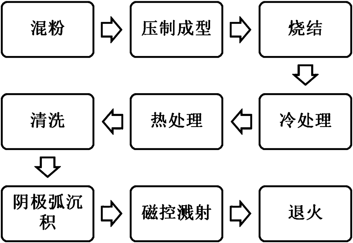
Method used
Image

Examples
Embodiment 1
[0041] In the present embodiment, the material composition (wt%) for preparing the valve seat ring is shown in Table 1 below:
[0042] Table 1
[0043]
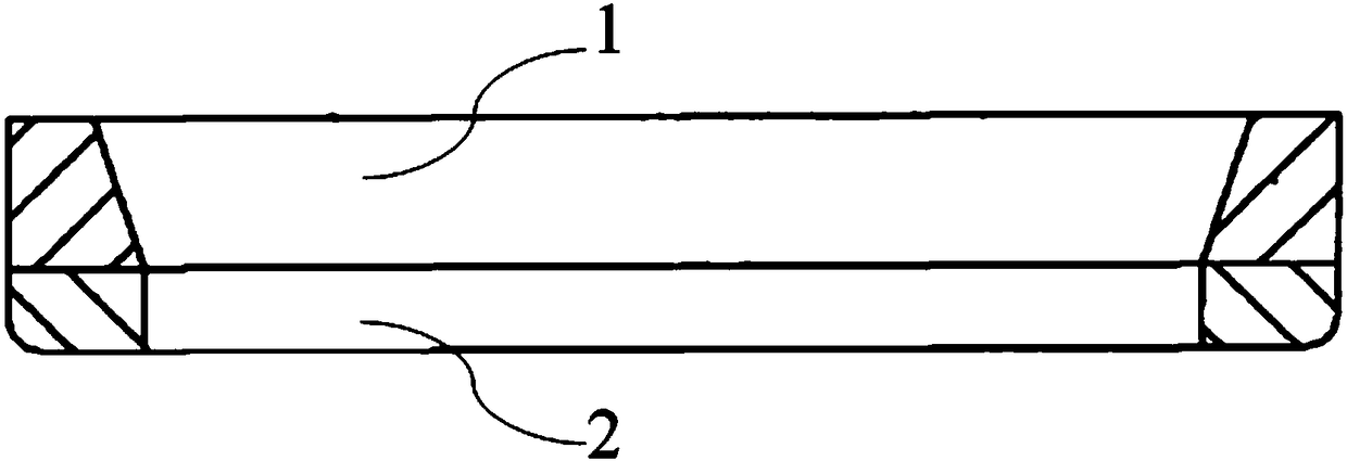
[0044] The valve seat was prepared according to the above material composition and the valve seat preparation process, and related performance tests were carried out on the valve seat: after surface treatment, a density test was first performed, and the test showed that the valve seat The density is 7.85g / cm 3 Then adopt the Rockwell hardness method to carry out the hardness test, the test shows that the hardness of the upper seat ring 1 of the valve seat ring is 46HRC; then adopt the Vickers hardness method to carry out the hardness test, the test shows that the surface hardness of the valve seat ring is 830HV. .2; Finally, a ball mill type friction and wear testing machine is used to carry out a friction test, and the test shows that the coefficient of friction of the valve seat ring is 0.15.
Embodiment 2
[0046] In the present embodiment, the material composition (wt%) for preparing the valve seat ring is shown in Table 2 below:
[0047] Table 2
[0048]
[0049] Prepare the valve seat according to the material composition shown in Table 2 and the valve seat preparation process, and carry out relevant performance tests on the valve seat: after surface treatment, first carry out density test, the test shows The density of the valve seat ring is 8.04g / cm 3 Then adopt the Rockwell hardness method to carry out the hardness test, the test shows that the hardness of the upper seat ring 1 of the valve seat ring is 48HRC; then adopt the Vickers hardness method to carry out the hardness test, the test shows that the surface hardness of the valve seat ring is 854HV. .2; finally adopt the ball mill type friction and wear testing machine to carry out the friction test, the test shows that the friction coefficient of the valve seat ring is 0.12.
Embodiment 3
[0051] In the present embodiment, the material composition (wt%) of preparing valve seat is as shown in table 3 below:
[0052] table 3
[0053]
C
Si
mn
S
co
Cr
Mo
V
Cu
Fe
upper layer
1.1
0.5
2.0
1.0
4.0
7.0
7.5
3.0
20.0
margin
lower level
0.9
1.0
1.1
22.0
margin
[0054] The valve seat was prepared according to the above material composition and the valve seat preparation process, and related performance tests were carried out on the valve seat: after surface treatment, a density test was first performed, and the test showed that the valve seat The density is 8.18g / cm 3 Then adopt the Rockwell hardness method to carry out the hardness test, the test shows that the hardness of the upper seat ring 1 of the valve seat ring is 51HRC; then adopt the Vickers hardness method to carry out the hardness test, the test shows that the surface hardness of the...
PUM
| Property | Measurement | Unit |
|---|---|---|
| Density | aaaaa | aaaaa |
| Density | aaaaa | aaaaa |
| Density | aaaaa | aaaaa |
Abstract
Description
Claims
Application Information