Sensitized cytochrome c optical fiber sensing device and method

A cytochrome, optical fiber sensing technology, applied in the field of biomedical optical sensing technology design, can solve the problems of low detection limit, expensive, insufficient to track apoptosis in situ, etc., to enhance the sensitivity of evanescent wave and optical fiber sensing Enhanced effect

Active Publication Date: 2018-10-02
JINAN UNIVERSITY
View PDF9 Cites 10 Cited by
  • Summary
  • Abstract
  • Description
  • Claims
  • Application Information

AI Technical Summary

Problems solved by technology

The lowest limit of detection (LOD) in most of these methods is only 10 -12 M, is not enough to track the occurrence of apoptosis in situ, and requires expensive, large-scale instruments

Method used


Image

  • Sensitized cytochrome c optical fiber sensing device and method
  • Sensitized cytochrome c optical fiber sensing device and method
  • Sensitized cytochrome c optical fiber sensing device and method

Examples


Embodiment 1

[0039] Optical fiber sensing technology uses optical fiber physical media with a scale of hundreds of microns and light waves as information carriers. It has the advantages of low cost, compact structure, high sensitivity, remote monitoring, corrosion resistance, and strong biocompatibility. It has become the fastest growing in recent years. One of the biosensing technologies. In the relevant reports of fiber optic biosensing research, high performance fiber optic interferometer has become a research hotspot. The most representative one is the tapered micro-nano optical fiber interferometer sensor developed in recent years. In addition to the characteristics of conventional optical fiber sensors, this type of optical fiber sensor can also use the evanescent wave mode excited by it that is sensitive to the surrounding environment , not only greatly enriched its detection objects, but also improved the measurement accuracy. It has very broad application prospects in the field o...

Embodiment 2

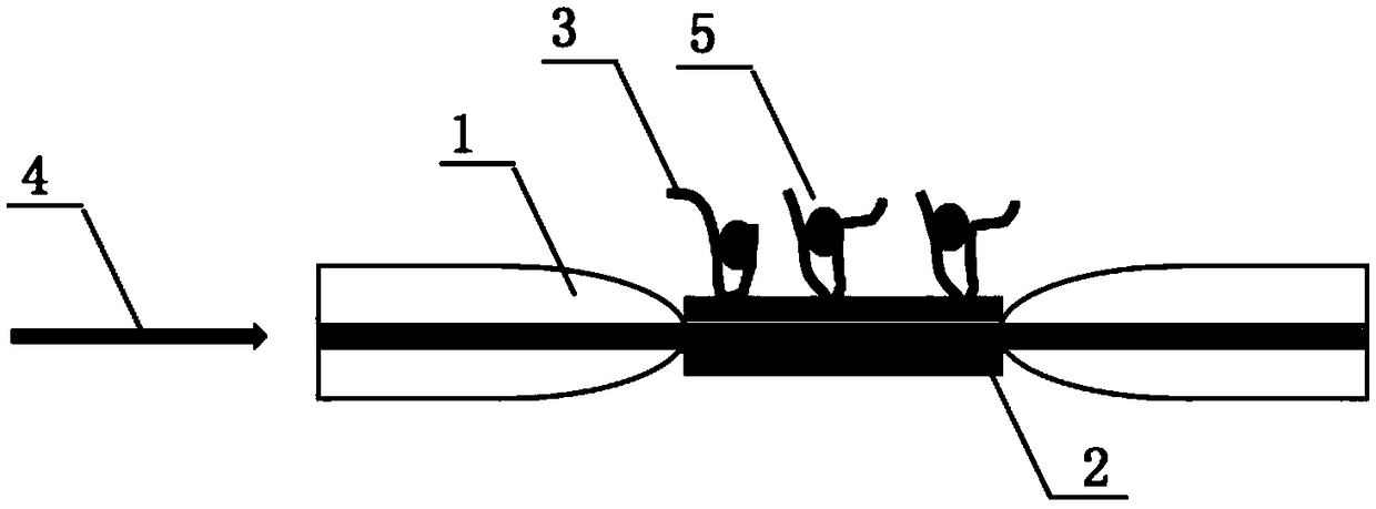
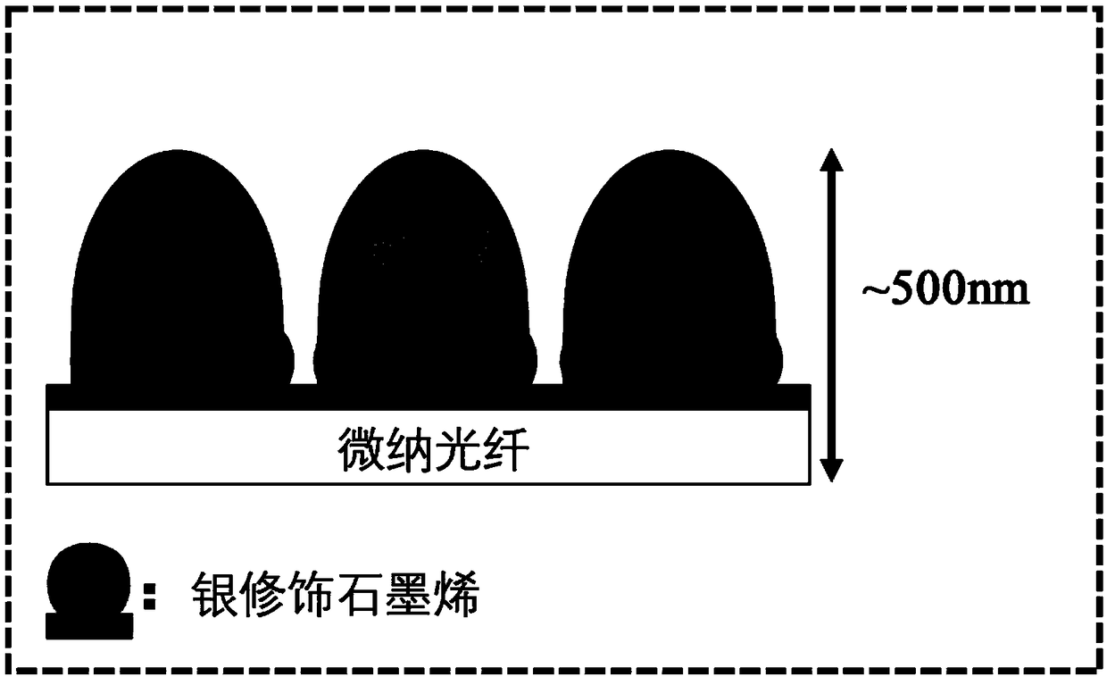
[0044] like figure 1 As shown, the present embodiment provides a method for sensing sensitized cytochrome c optical fiber, the method comprising: drawing the photosensitive optical fiber into a tapered micro-nano optical fiber 1 with a diameter of 10.5 microns on a flame, and drawing the tapered micro-nano optical fiber 1 The optical fiber 1 is fused with a single-mode optical fiber to make an optical fiber sensing probe; the graphene interface 2 modified by silver nanoparticles is assembled on the side of the tapered micro-nano optical fiber 1 to form a single-layer film, and the DNA is adapted to the surface through non-covalent bonding. The ligand 3 is immobilized on the surface of the graphene interface 2; after the DNA aptamer 3 is immobilized, the optical fiber sensing probe is immersed in the culture medium containing the cells, and the light source 4 is input into the tapered micro-nano optical fiber. The evanescent wave on the side of the micro-nano optical fiber 1 is...


PUM

PropertyMeasurementUnit
Diameteraaaaaaaaaa
Diameteraaaaaaaaaa

Abstract

The invention discloses a sensitized cytochrome c optical fiber sensing device and method. The device comprises a tapered micro-nano optical fiber, a graphene interface and a DNA aptamer. A transitionarea and a homogeneous area of the tapered micro-nano optical fiber form an interference structure, and the tapered micro-nano optical fiber is welded with a single-mode optical fiber to form an optical fiber sensing probe. The graphene interface is a silver nanoparticle modified graphene interface, and is assembled into a single layer film on a side of the tapered micro-nano optical fiber. The DNA aptamer is fixed on the surface of the graphene interface by non-covalent bonding. The optical fiber sensing probe is immersed into a culture solution containing cells after the DNA aptamer is fixed, also a light source is input into the tapered micro-nano optical fiber, and the characteristic that the evanescent wave on the side of the tapered micro-nano optical fiber is sensitive to the external environment change is utilized to detect the aptamer conformational change caused by specific binding of cytochrome c molecules and the DNA aptamer. The device and method provided by the inventioncan realize extracellular in situ measurement of cytochrome c in the human body and avoid invasive injury and toxicity to cells.

Description

technical field [0001] The invention relates to an optical fiber sensing device, in particular to a sensitized cytochrome c optical fiber sensing device and method, belonging to the technical design field of biomedical optical sensing. Background technique [0002] Cytochrome c, as a multifunctional enzyme, is an important electron transporter. During apoptosis, cytochrome c is released from mitochondria and then from cells when they rupture, and its release is an important signal of programmed cell death - apoptosis. In clinical disease diagnosis, once the pathological state is caused by heart failure, DNA damage, cytoskeleton destruction or foreign cell invasion, cytochrome c in mitochondria can be released into the blood by damaging the permeability of mitochondria. Therefore, the monitoring of cytochrome c not only provides a biomarker for apoptosis, but also has great significance for understanding certain diseases at the cellular level. [0003] The laboratory's exis...

Claims


Application Information

Patent Timeline
IPC IPC(8): G01N21/45
CPCG01N21/45G01N2021/458
Inventor 黄赟赟李宏韬关柏鸥
Owner JINAN UNIVERSITY
Why Eureka
Try Eureka