Radial magnetizing unilateral magnetron resistance spot welding device

A magnetron resistance and spot welding device technology, which is applied in the direction of resistance welding equipment, welding equipment, metal processing equipment, etc., can solve the problems of easy generation of air holes, cracks, large size of magnetron device, low joint performance, etc., and achieve lower temperature Gradient, clamp loosening prevention, effect of increasing nugget diameter

Active Publication Date: 2018-10-16
SHANGHAI JIAO TONG UNIV
View PDF6 Cites 8 Cited by
  • Summary
  • Abstract
  • Description
  • Claims
  • Application Information

AI Technical Summary

Problems solved by technology

[0002] The wide application of lightweight materials such as high-strength steel and aluminum alloy and the connection of dissimilar materials has brought many challenges to the existing resistance spot welding process: high-strength steel has a high carbon equivalent, and it is easy to form brittle, hard, and coarse weld nuggets during the rapid cooling process. The lath-like martensite structure greatly reduces the strength and fatigue performance of the welded joint; while the aluminum alloy has good thermal and electrical conductivity and a large linear expansion coefficient, defects such as pores and cracks are prone to occur during the welding process, making the joint performance low, and the joint The forming process consumes a lot of energy
Although multi-pulse, post-weld heat treatment and other means can alleviate the brittleness and hardness of the joint structure and interface failure, it needs to consume more resources and the process is relatively complicated.
The existing magnetron resistance spot welding devices are all axially axisymmetric magnetic fields, resulting in a very small radial component of the welding area. It is necessary to adopt bilateral symmetrical arrangements to have sufficient magnetic field strength in the radial direction parallel to the effective welding area and the plate, resulting in The size of the magnetic control device is large, and the effect of electromagnetic stirring is limited

Method used


Image

  • Radial magnetizing unilateral magnetron resistance spot welding device
  • Radial magnetizing unilateral magnetron resistance spot welding device
  • Radial magnetizing unilateral magnetron resistance spot welding device

Examples


Embodiment 1

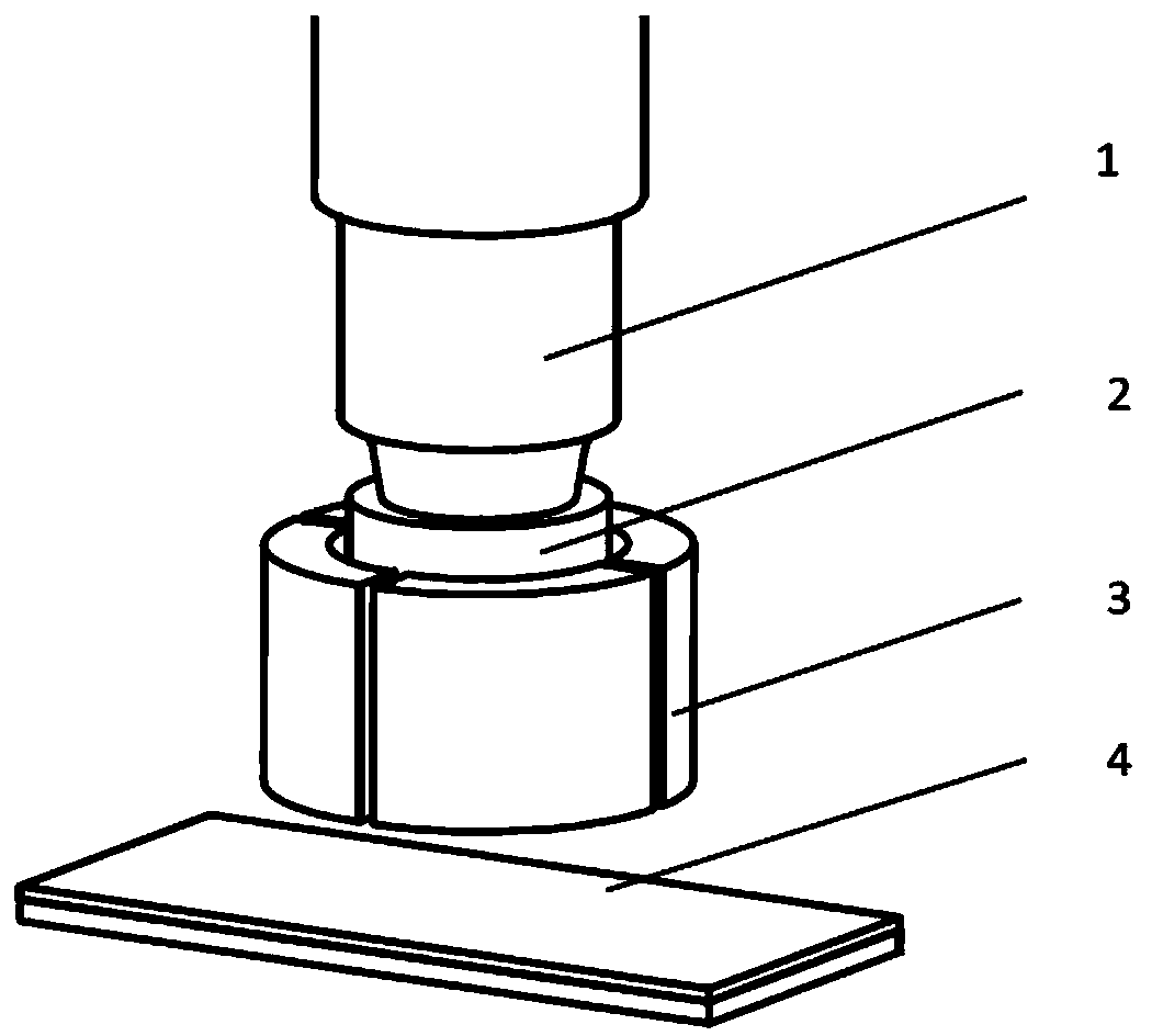
[0028] like figure 1 As shown, it is a four-lobed radial magnetron device related to this embodiment, which includes: a single-sided electrode rod 1, an electrode cap 2, and a permanent magnet unit 3, wherein: the electrode cap 2 is arranged on the free side of the electrode rod 1 At the end, the permanent magnet unit 3 is fixedly arranged at the end of the electrode rod 1, so that the lower end of the permanent magnet unit is 0-3mm away from the end of the electrode cap.

[0029] The workpiece 4 to be welded in this embodiment is a stainless steel plate 304, and its thickness matching is: 1.5mm+2.5mm.

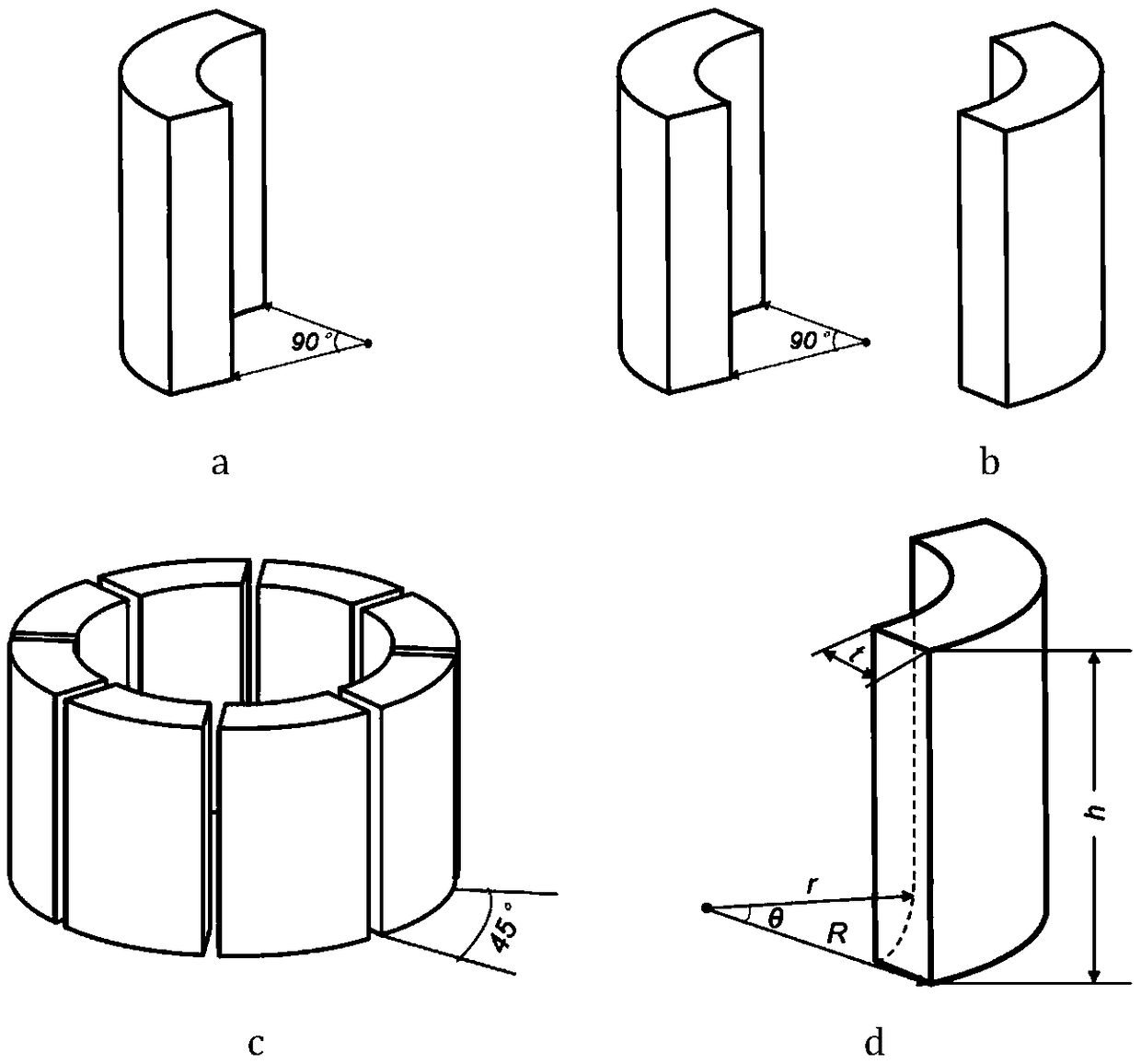
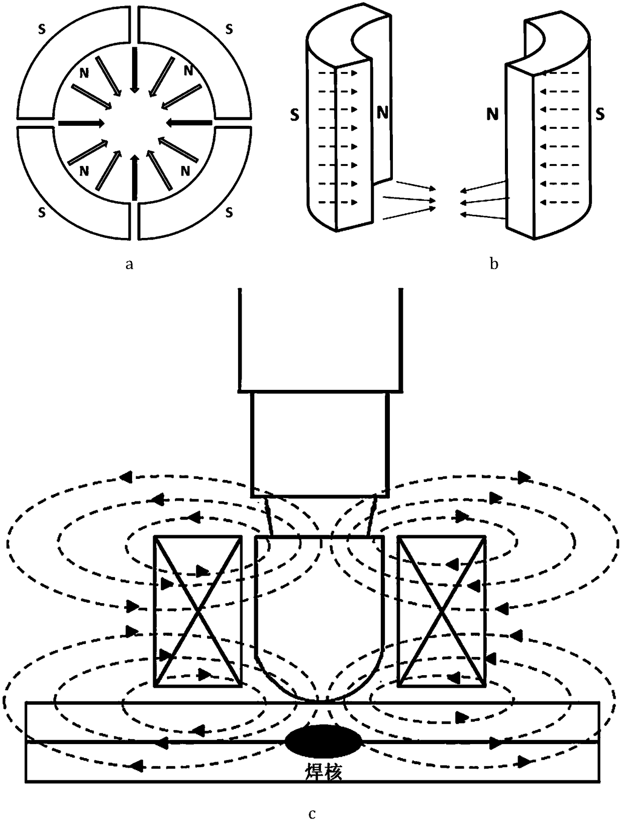
[0030] like figure 2 d and image 3 As shown in a to c, the permanent magnet unit 3 in this embodiment is four permanent magnet units with an arc of 90°, the wall thickness is 5mm, and the height is 15mm, and the four permanent magnet units are placed on the electrode cap in a symmetrical manner to the center Around, the permanent magnet is magnetized along the axial direc...

Embodiment 2

[0037] like Figure 4 As shown, it is the eight-lobed radial magnetization single-side magnetron resistance spot welding device of the present embodiment. The difference compared with Embodiment 1 is that the permanent magnet unit 3 is eight pieces with a 45° arc. The permanent magnet unit, such as figure 2 as shown in c.

[0038] Compared with Embodiment 1, the further technical effect of this embodiment lies in the use of denser permanent magnet units, so that the applied magnetic field has better consistency in all directions, and the quality of the nugget can be improved more stably. In the case of interference, the eight-lobed permanent magnet unit can expand and contract part of the unit according to the interference position, so that as many permanent magnet units as possible can be in contact with the workpiece to be welded, so that the effective magnetic field can reach the best state, and the magnetic control effect is also slightly enhanced. . Through the action...

Embodiment 3

[0040] like Figure 5 As shown, it is the two-lobed radial magnetization single-side magnetron device of this embodiment, and its difference compared with Embodiment 1 is that the permanent magnet unit 3 is two radial radial magnetrons with an arc of 90°. Magnetized permanent magnet units such as figure 2 as shown in b.

[0041] Compared with Embodiment 1, the technical effect of this embodiment is to further reduce the volume of the magnetic control device, the total volume of the device is only 50% of that of Embodiment 1, and reduce possible interference problems in the production process. Experiments show that using two Compared with the embodiment 1, the magnetic control effect is only slightly decreased. Under the action of electromagnetic stirring, the grain refinement of the microstructure is obvious, the diameter of the nugget of the joint is increased by 13%, the mechanical properties of the welded joint are improved by 17%, and the fracture energy absorption is i...


PUM

PropertyMeasurementUnit
angleaaaaaaaaaa
thicknessaaaaaaaaaa
heightaaaaaaaaaa

Abstract

The invention discloses a radial magnetizing unilateral magnetron resistance spot welding device. The device comprises at least one permanent magnet unit for generating a radial magnetic field, an electrode pole and an electrode cap; the electrode cap is arranged at the tail end of the electrode pole; the permanent magnet units are distributed around the electrode cap in a central symmetry manner;a magnetic line penetrates through symmetric shafts; the bottoms of the permanent magnet units are nugget areas; and the acting directions of effective stirring magnetic fields in the nugget areas are radial directions. The permanent magnet units adopt a radial magnetizing mode, and only need to be arranged on any single side to obtain higher radial effective magnetic fields in the effective welding areas; during welding, radial external magnetic fields and the Lorentz force generated by axial welding current perform non-contact electromagnetic stirring on nugget molten metal, so that metal fluids are rotated at high speed to scour nugget boundaries, the nugget diameters are increased, and the temperature gradient is reduced; and in the cooling crystallization phase, liquid-state metal continuously performs inertia flowing, so that the welding joint quality is prominently improved through crushing dendritic crystal refining grain structures.

Description

technical field [0001] The invention relates to a technology in the field of electromagnetic welding, in particular to a radially magnetized single-side magnetron resistance spot welding device. Background technique [0002] The wide application of lightweight materials such as high-strength steel and aluminum alloy and the connection of dissimilar materials has brought many challenges to the existing resistance spot welding process: high-strength steel has a high carbon equivalent, and it is easy to form brittle, hard, and coarse weld nuggets during the rapid cooling process. The lath-like martensite structure greatly reduces the strength and fatigue performance of the welded joint; while the aluminum alloy has good thermal and electrical conductivity and a large linear expansion coefficient, defects such as pores and cracks are prone to occur during the welding process, making the joint performance low, and the joint The forming process consumes a lot of energy. Although ...

Claims


Application Information

Patent Timeline
Patent Type & Authority Applications(China)
IPC IPC(8): B23K11/11
CPCB23K11/11
Inventor 祁麟李永兵李方舟楼铭雷海洋
Owner SHANGHAI JIAO TONG UNIV
Why Eureka
Try Eureka