Method for manufacturing a part or a supported microstructure by laser exposure of a metal oxalate layer
A technology of oxalate and microstructure, which is applied in the field of ceramic or composite parts or manufacturing supporting metal, manufacturing metal, ceramic or composite microstructure, which can solve the problems of discontinuity of parts, insufficient mechanical strength of parts, etc., and the method is simple, The effect of method economy
- Summary
- Abstract
- Description
- Claims
- Application Information
AI Technical Summary
Problems solved by technology
Method used
Image

Examples
Embodiment 1
[0164] Embodiment 1: Fabricate a metal microstructure with a periodic pattern according to the method of the present invention
[0165] According to the procedure described by K. Kiryukhina et al. in Scripta Materialia, 2013, 68, 623-626, corresponding to the formula Ag 2 C 2 o 4 Silver oxalate in the form of a powder of acicular particles, wherein the average length of the acicular particles is about 5 μm, and the average width is 1 μm.
[0166] 1 g of this oxalate was mixed with 4 g of ethylene glycol in an agate mortar. The resulting mixture was then placed in an ultrasonic bath to provide a good dispersion of the particles in ethylene glycol. The viscosity of the mixture was measured to be about 32 cP under the conditions defined in the present invention.
[0167] 3 drops (volume of about 1.5 ml) of the above-obtained suspension were deposited on a glass slide as a substrate, wherein the size of the slide glass was 3 cm×2.5 cm, to produce a smear. The assembly was place...
Embodiment 2
[0172] Embodiment 2: Fabricate a metal microstructure with a periodic pattern according to the method of the present invention
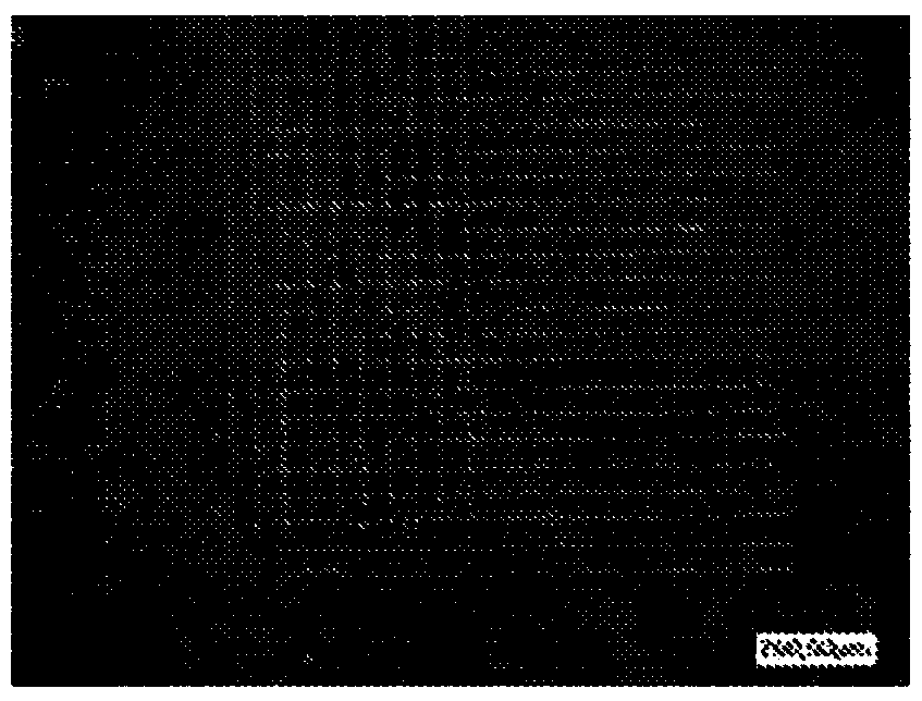
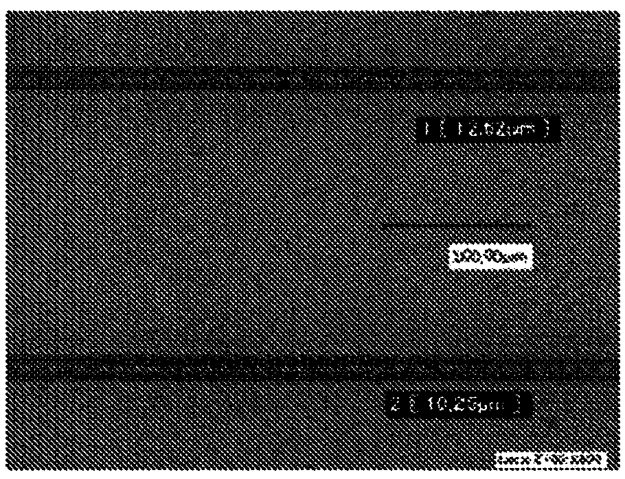
[0173] The microstructure obtained according to Example 1 was heated to a temperature of about 300° C. using a furnace with heating elements at a heating rate of about 150° C. / h. The microstructure was kept at 300°C for 1 hour and then cooled to ambient temperature at a cooling rate of about 150°C / h. This additional step makes possible the sintering of the silver wire as obtained in Example 1. A silver metal grid comprising silver wires with a width of about 10 μm and a thickness of about 5 μm is thus obtained.
[0174] The resulting microstructure remained transparent.
Embodiment 3
[0175] Example 3: Fabrication of metal microstructures with linear patterns according to the method of the present invention
[0176] The microstructure was prepared under the same conditions as those described in Example 1, except that the displacement rate of the sample was 1 mm / s instead of 5 mm / s, and the pattern to be irradiated was a line with a length of 15 mm instead of 200 ×200μm 2 grid.
[0177] Furthermore, ten consecutive passes according to the pattern were performed without step iii) (ie without removing the layer in the unheated area).
[0178] Silver metal lines with a width of about 15 μm and a thickness of about 5 μm were thus obtained.
[0179] The conductivity of the wire was measured by the two-point method using a Keithley brand multimeter, which was about 7.5 x 10 5 S m -1 .
[0180] Therefore, the method of the present invention can impart electrical conductivity to a glass substrate while maintaining its optical transparency.
PUM
| Property | Measurement | Unit |
|---|---|---|
| size | aaaaa | aaaaa |
| thickness | aaaaa | aaaaa |
| diameter | aaaaa | aaaaa |
Abstract
Description
Claims
Application Information
 - R&D
- Intellectual Property
- Life Sciences
- Materials
- Tech Scout
- Unparalleled Data Quality
- Higher Quality Content
- 60% Fewer Hallucinations
Browse by: Latest US Patents, China's latest patents, Technical Efficacy Thesaurus, Application Domain, Technology Topic, Popular Technical Reports.
© 2025 PatSnap. All rights reserved.Legal|Privacy policy|Modern Slavery Act Transparency Statement|Sitemap|About US| Contact US: help@patsnap.com